48 FLOWSIC500 · Operating Instructions · 8025733/1GMJ/V4-2/2022-07 · © SICK Engineering GmbH
Installation
Subject to change without notice
3.4.2 Criteria for electrical connection
Installation work → p. 39, §3.3 must be completed.
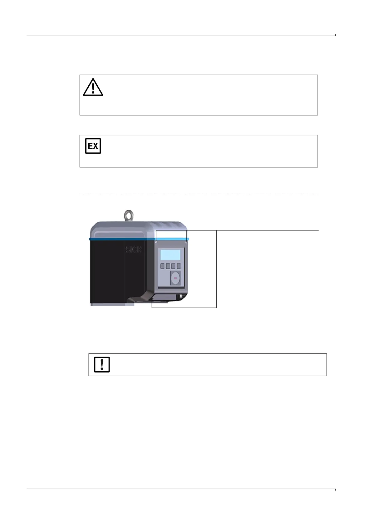
3.4.3 Opening and closing the electronics cover
Opening the electronics cover
1 Loosen the 4 screws (captive) on the electronics cover using an SW3 Allen key.
Fig. 16 Position of electronics cover screws
2 Open the electronics cover.
Closing the electronic cover
1 Close the electronics cover.
2 Screw the electronics cover tight again.
Tightening torque: 2.0 Nm (18 lbf in)
WARNING: Risk of explosion - hazard for intrinsic safety
▸
The following work may only be carried out by skilled technicians familiar
with the special characteristics of the intrinsic safety of the ignition
protection type and who have knowledge of the relevant standards and
regulations for interconnection of intrinsically safe power circuits.
The Ex i terminal compartment of the FLOWSIC500 can be accessed after the
electronics cover has been opened. The cover may also be opened in the
hazardous area when under voltage. However, safe separation between the
various intrinsically safe power circuits must not be breached.
4 screws
▸
Make sure no battery and display cables are pinched.