Installation
FLOWSIC500 · Operating Instructions · 8025733/1GMJ/V4-2/2022-07 · © SICK Engineering GmbH 49
Subject to change without notice
3.4.4 Rotating the control unit
1 Open the electronics cover (→ p. 46, §3.4)
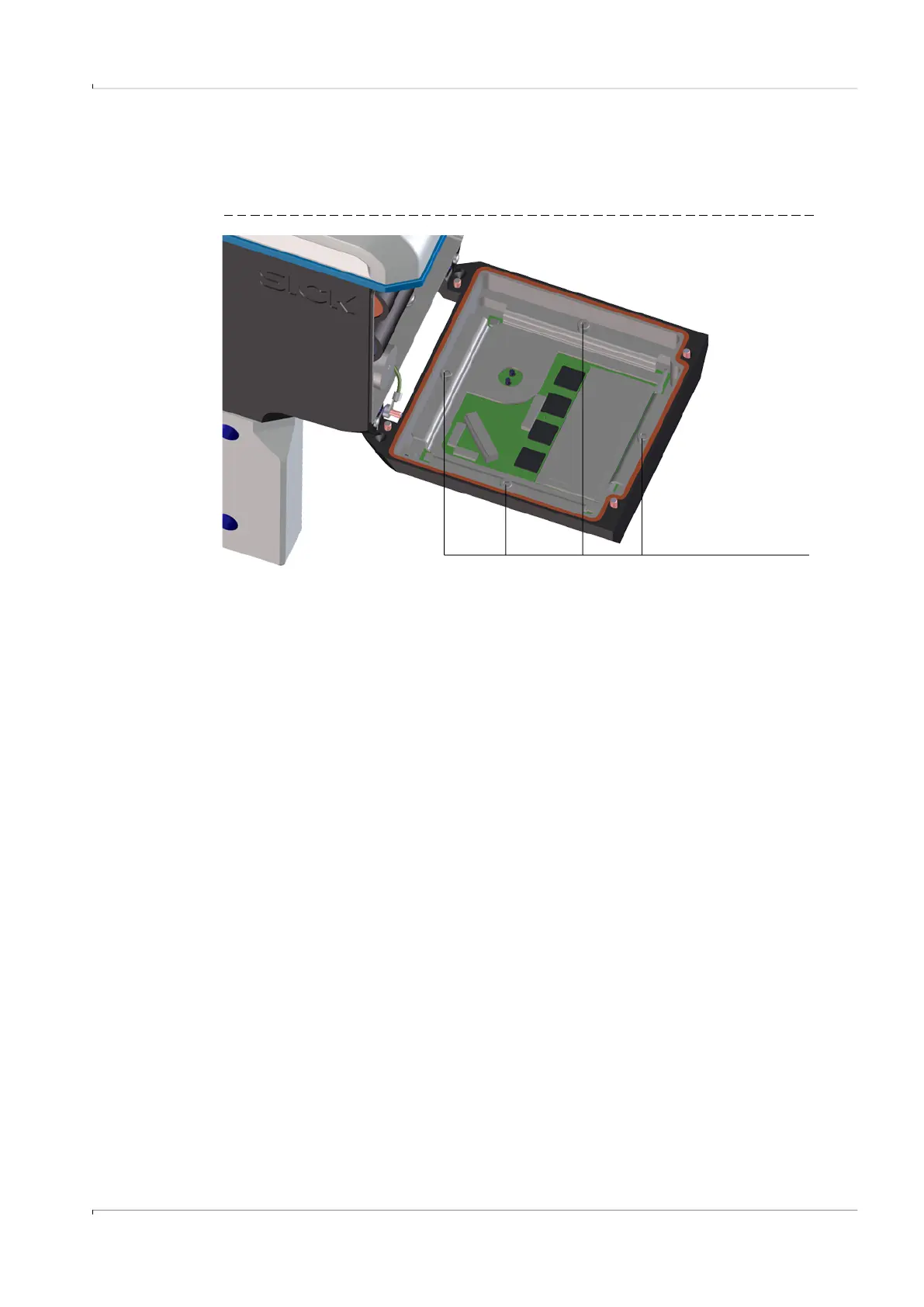
2 Loosen the 4 display screws with an SW3 Allen key, → Fig. 17.
Fig. 17 Position of display screws
3 Check the display seal for intactness and correct fitting.
4 A new seal is available as spare part when the display seal is damaged
(Part No. 2095177).
5 Rotate the display in the desired direction and reposition.
6 Tighten the display screws evenly.
Tightening torque: 1.0 Nm (9 lbf in)
7 Close the electronics cover again.
4 display screws