Installation
FLOWSIC500 · Operating Instructions · 8025733/1GMJ/V4-2/2022-07 · © SICK Engineering GmbH 43
Subject to change without notice
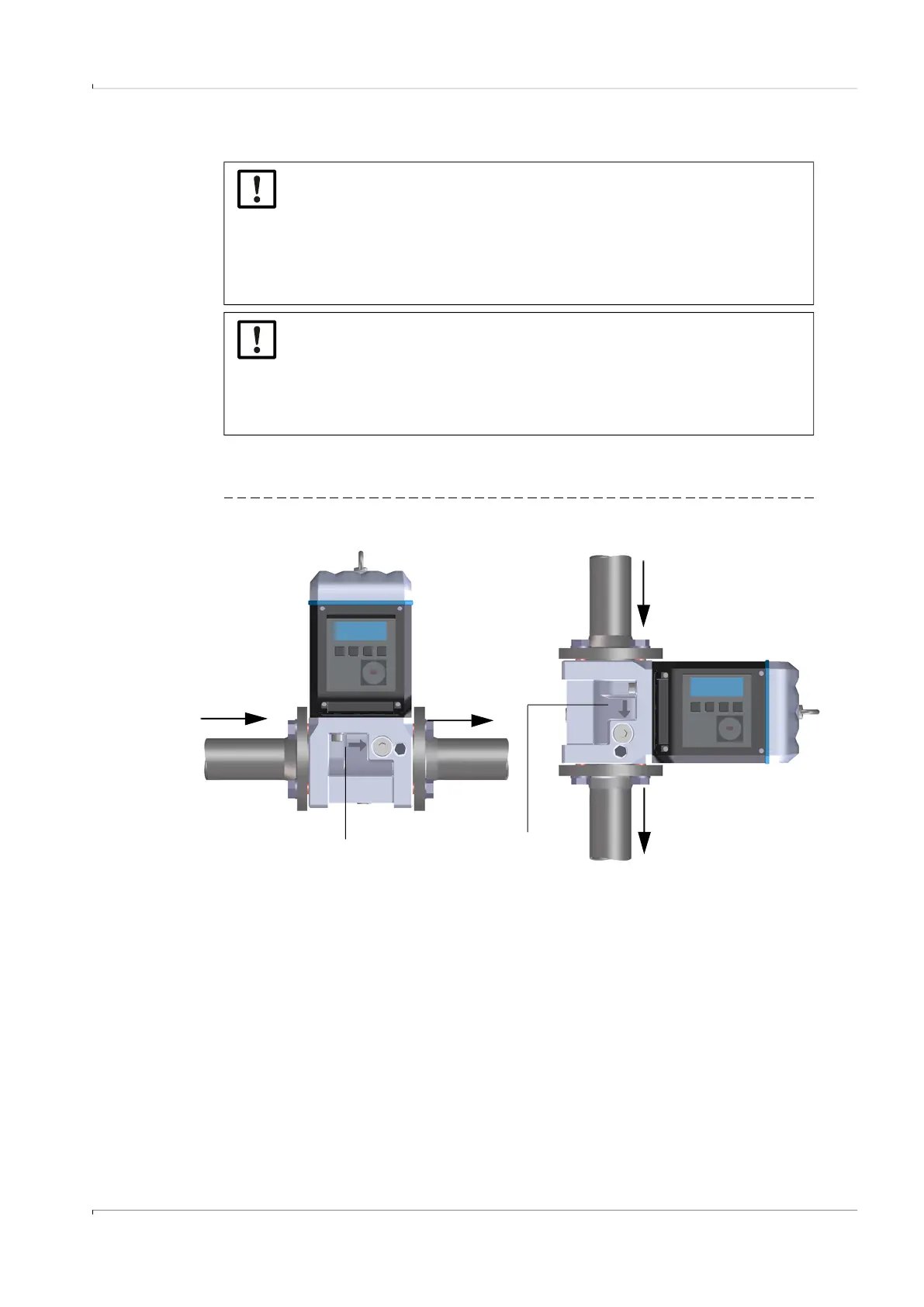
3.3.3 Fitting in the pipeline
The FLOWSIC500 can be installed horizontal or vertical.
The control unit can be rotated ± 90° (→ p. 49, §3.4.4).
Fig. 13 Installation examples
NOTICE:
The lifting lug is designed for transporting the measuring device only.
Do not lift or transport the FLOWSIC500 with additional loads using this lug.
▸
The FLOWSIC500 must not swing or tilt on the hoisting equipment during
transport.
▸
The FLOWSIC500 must not turn during transport otherwise the lifting lug
could be screwed out.
NOTICE: Observe the gas flow direction
The prescribed flow direction is marked on the adapter with an arrow.
Arrow direction and gas flow direction must match.
▸
Install the FLOWSIC500 in flow direction.
The device signals a malfunction when the FLOWSIC500 is installed against
the prescribed flow direction.
Marking for flow direction
Direction of gas flow