Product description
FLOWSIC500 · Operating Instructions · 8025733/1GMJ/V4-2/2022-07 · © SICK Engineering GmbH 31
Subject to change without notice
2.8 Parameter protection
2.8.1 Parameter locking switch
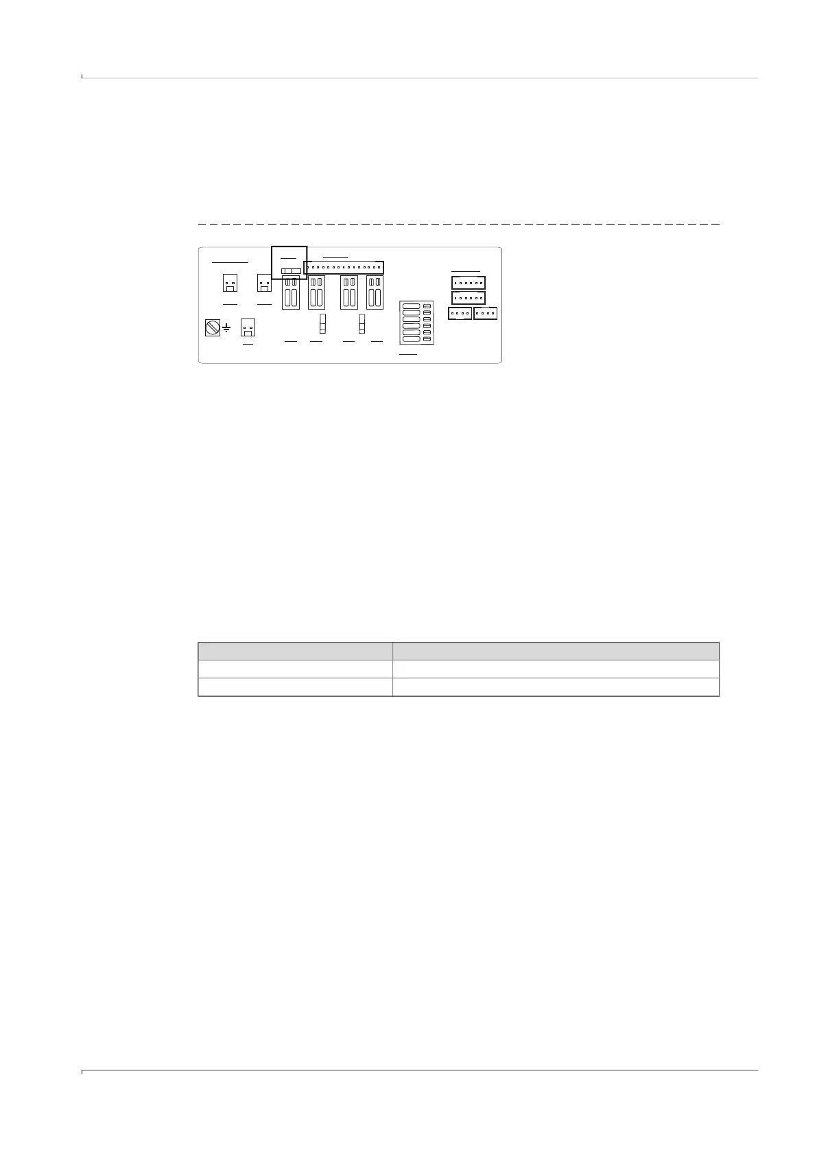
A parameter locking switch is located on the circuit board to secure the custody relevant
parameters. This covers all values that influence volume metering and volume conversion.
Fig. 7 Parameter locking switch on the circuit board
The parameter locking switch is secured by the terminal compartment cover and a seal.
2.8.2 Metrology logbook
Selected custody relevant parameters can be modified when the parameter locking switch
is closed and after logging in as authorized user.
An entry in the metrology logbook is generated to ensure the traceability of these
parameter changes. The entry contains the timestamp, old and new value, totalizer level V
(for gas flow meters) or Vb (for gas flow meters with device option volume conversion) and
the logged on user.
The Metrology logbook can have a maximum of 100 entries. The FLOWSIC500 switches to
status “Warning” when the Metrology logbook is full.
The Metrology logbook can be cleared when the parameter locking switch is open.
Parameter changes to the following parameters are entered in the Metrology logbook as
long as entries are possible.
EXT. POWER
BAT1
N.c.
DO3
DO0
+-
RS485
*
-
+
-
+
A
B
P1
P2
T1
T2
SENSORS
DISPLAY
LOCK
OFF ON
5..12V
NAMUR
4,5..16V
1.5 mm²
(AWG 16)
W
R :100
S
2..16V
2..16V
4074419
DO2
*Optional
V see module
CC
.
OC
NAM
UR
2..16V
DO1
+-
BAT2
+-
+-
OC
NAM
UR
+- +-
Table 5 Custody relevant parameters - gas flow meter
Parameter Description
Max. reverse flow volume Buffer volume for reverse flow
Symbols for measured value displays Symbols used on the display (formula symbols)