124 FLOWSIC500 · Operating Instructions · 8025733/1GMJ/V4-2/2022-07 · © SICK Engineering GmbH
Maintenance and meter exchange
Subject to change without notice
7.4.10 Perform a leak tightness check
After each exchange of the gas flow meter, the correct installation of the gas flow meter and
the leak tightness of the measuring device has to be checked.
To check the leak tightness, the corresponding test cap for the respective meter size is
needed (→ p. 114, §7.4.4).
14 After a successful leak tightness check, connect the replacement gas flow meter to
the electric system, see §3. 4 “Electrical installation”.
15 If desired, upload the configuration of the previously installed gas flow meter to the
replacement gas flow meter (→ p. 116, §7.4.6).
16 Checking the function of the new gas flow meter, → p. 131, §7.4.12.
17 If necessary, secure metrologically (→ p. 131, §7.4.13).
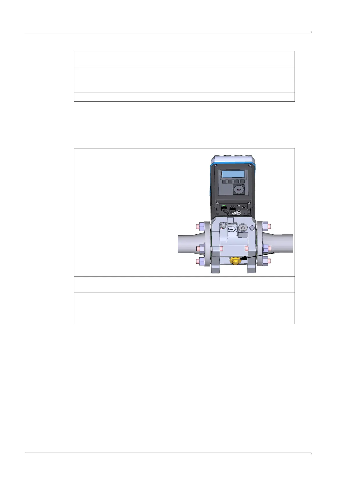
1 First screw the test cap for the
respective meter size in manually.
2 Then tighten the test cap with the
socket wrench until the test cap is
completely screwed in.
3 Slowly increase the pressure in the device (max. gradient 3 bar/min or 45 psi/min) up
to the line pressure.
4 Apply leak detection spray to the opening of the test cap.
5 Check over at least 15 min whether gas escapes at the opening of the test cap
– When no gas escapes from the opening of the test cap, see → p. 125, §7.4.10.1.
– When gas escapes from the opening of the test cap, see → p. 125, §7.4.10.2.