Installation
FLOWSIC500 · Operating Instructions · 8025733/1GMJ/V4-2/2022-07 · © SICK Engineering GmbH 61
Subject to change without notice
3.5.2 Installing the pressure sensor
A three-way test valve is normally fitted to be able to test the pressure sensor also when
installed.
▸
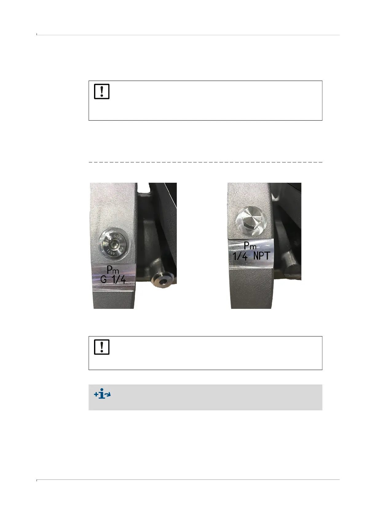
Before installing a pressure sensor, check if there is a G 1/4" or NPT 1/4" thread on the
meter body.
▸
The thread type is marked on the meter body:
Fig. 30 Marking on meter body
▸
When the meter body has an NPT 1/4“ thread, screw in the adapter from NPT 1/4“ to G
1/4“ (Part No. 2075562) before using the accessory parts available from SICK.
Variant 1: Installation with test valve BDA04 (up to -20 °C dynamic, up to -30 °C static)
1 Remove the dummy plug on the pressure measuring port marked “P
m
”.
2 When the meter body has an NPT 1/4“ thread, first screw in the adapter from NPT 1/4“
to G 1/4“ (Part No. 2075562).
3 Fit the test valve BDA04.
Pay attention to the alignment of the connection for the pressure sensor.
NOTICE: Fitting information
It is recommended to connect the pressure sensor with the three-way test
valve or with the FLOWSIC500 so that there is a downward slope from the
pressure sensor to the connection point and from the three-way test valve to
the FLOWSIC500.
Thread G 1/4“ Thread 1/4“ NPT
NOTICE:
The thread on the meter body is damaged when a wrong thread type is screwed
in.
Observe the marking on the meter body!
For details on installation with test valve BDA04, see manufacturer Operating
Instructions.
You will find the document on the delivered product CD.