60 FLOWSIC500 · Operating Instructions · 8025733/1GMJ/V4-2/2022-07 · © SICK Engineering GmbH
Installation
Subject to change without notice
2 Connect the plugs to the planned connections.
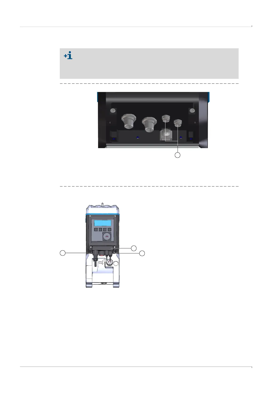
Fig. 28 Connections for pressure and temperature sensors
3 Push the plug-in connector cover over the plugs and fasten with both capstan screws.
Fig. 29 Fastening the plug-in connector cover
For meter sizes DN50 and DN80, it is recommended to connect the pressure
sensor to the right M8 connection and the temperature sensor to the left M8
connection.
The FLOWSIC500 automatically detects whether a pressure or temperature
sensor has been connected to a connection.
1 Connections for pressure and temperature sensors
1
1
1
2
1 Capstan screw
2 Plug-in connector cover