Installation
FLOWSIC500 · Operating Instructions · 8025733/1GMJ/V4-2/2022-07 · © SICK Engineering GmbH 59
Subject to change without notice
3.5 Installing the external pressure and temperature sensors
The adapter of FLOWSIC500 has measuring ports for pressure and temperature.
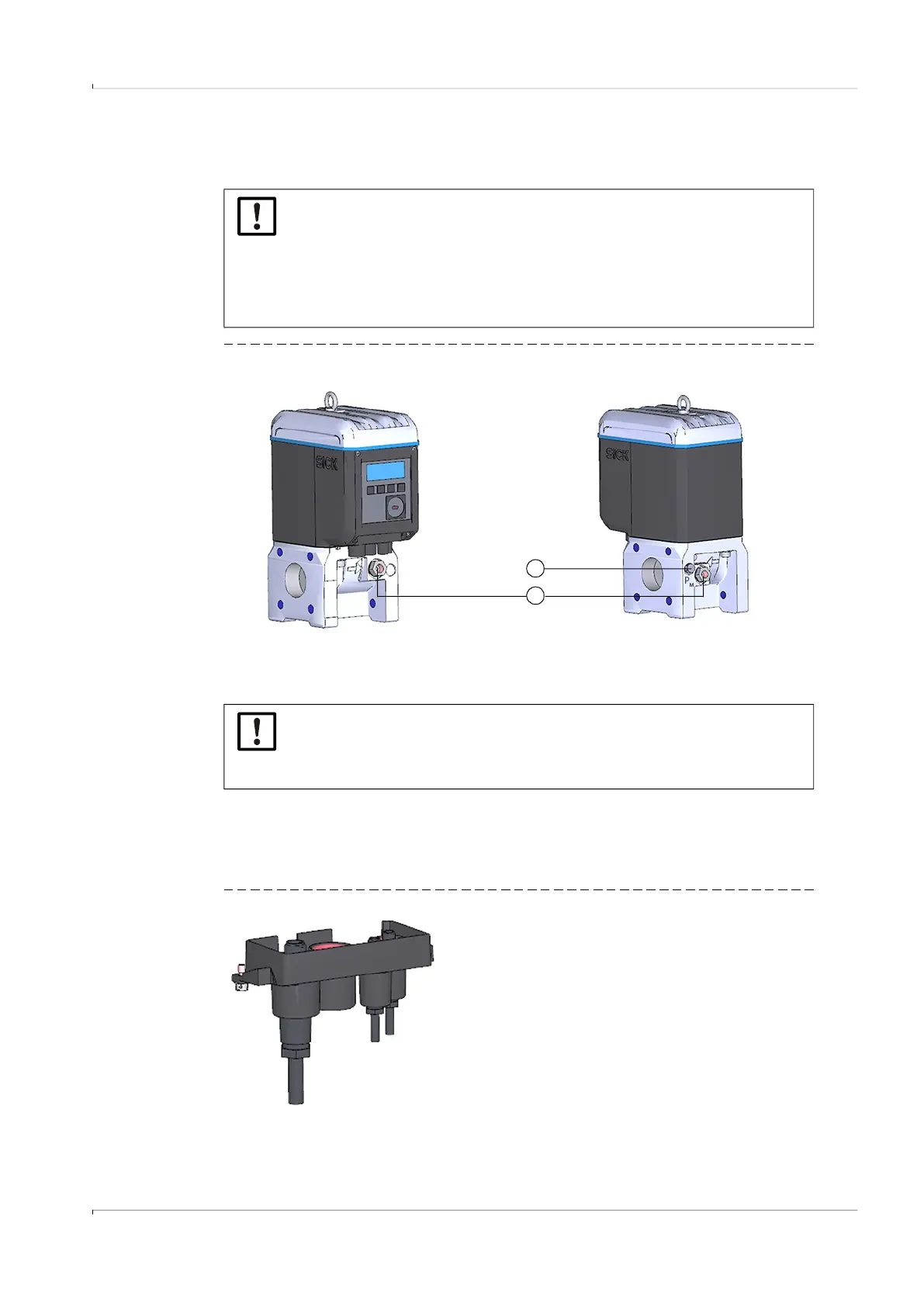
Fig. 26 Pressure and temperature measuring ports (front and rear side)
3.5.1
Fitting the plug-in connector cover
Fit the plug-in connector cover before installing the sensors.
1 Guide the sensor plugs through the openings in the plug-in connector cover.
Fig. 27 Plug-in connector cover
NOTICE:
▸
The pressure measuring port to be used for measurement is marked “P
M
”.
On meters with flow direction “left-right” (→), the marked pressure
measuring port is on the rear of the adapter, on meters with flow direction
“right-left” (←), it is on the front.
▸
The pressure and temperature sensors can only be replaced when the
parameter locking switch is open..
NOTICE: Ensure sufficient assembly clearance!
Ensure sufficient clearance to the wall or other components at the rear
measuring ports when installing the sensors.
The recommended minimum clearance to the wall is 0.3 m.
1
2
1 Pressure measuring port
2 Alternative temperature measuring ports