56 FLOWSIC500 · Operating Instructions · 8025733/1GMJ/V4-2/2022-07 · © SICK Engineering GmbH
Installation
Subject to change without notice
3.4.9 Operation with external power supply
3.4.9.1 Connecting the external power supply
1 Connect the external intrinsically safe power supply to the M12 plug-in connector of the
FLOWSIC500.
Safety-relevant parameters → p. 51, §3.4.6.
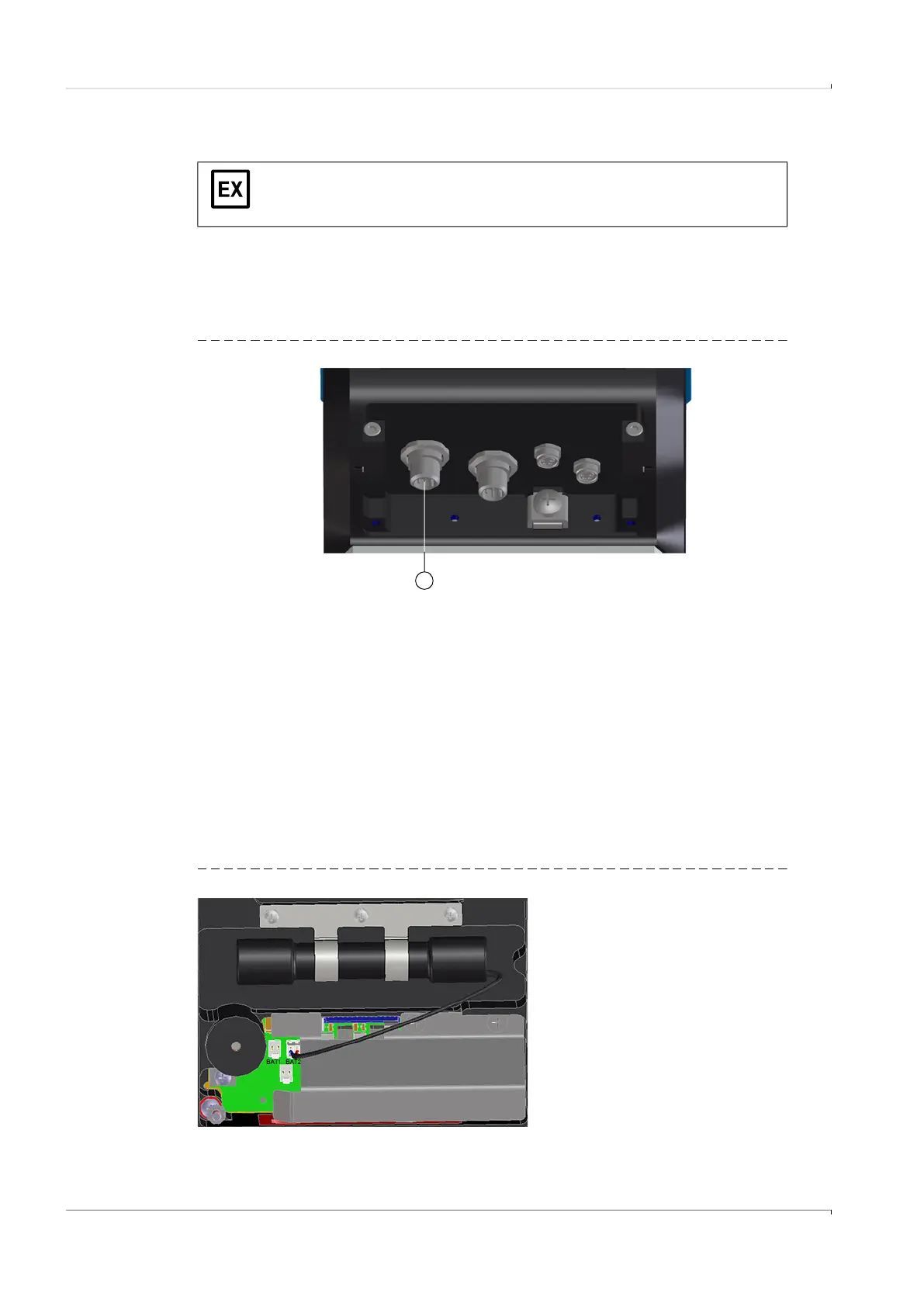
Fig. 23 Connection for external power supply underneath the gas flow meter
2 Switch the power supply on.
The FLOWSIC500 is initialized.
3 Measurement starts and the current measured value for the gas volume appears.
4 Set the date and time (→ p. 68, §4.2).
3.4.9.2 Connecting the backup battery
1 Open the electronics cover (→ p. 48, 3.4.3).
2 Connect the backup battery (Part No. 2065928) to connection BAT2 in the terminal
compartment (→ Fig. 24).
3 Close the electronics cover again.
Fig. 24 Connected backup batteries
The FLOWSIC500 is designed electrically intrinsically safe.
▸
After correct installation has been checked, the plug connections in the
hazardous area can be connected and disconnected under voltage as well.
1
1 External power supply and signal output