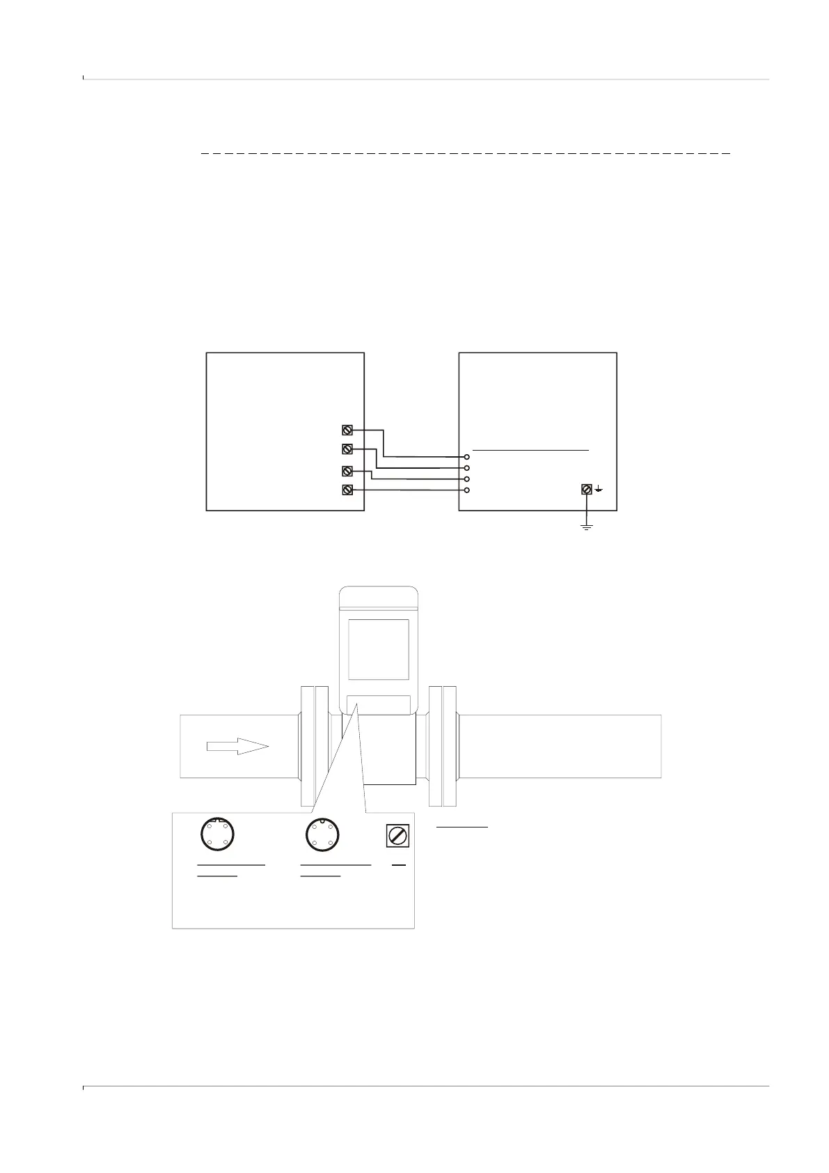
Fig. 77 Battery operation
+
-
+
-
3
4
21
3
4
21
For safety and entry parameters see
control drawing 9215965 for the USA and Canada
and control drawing 9215966 for the EU.
In the USA install in accordance with the NEC (ANSI/NFPA70)
In Canada install in accordance with CEC part 1,
in the EU in accordance with EN 60079-14.
National regulations must be observed!
PE
M12connector
B-coded
1 n.c.
2 n.c.
3 - DO 1 (passive)
4 + DO 1 (passive)
M12 connector
A-coded
1 + DO 2 (passive)
2 - DO 2 (passive)
3 - DO 3 (passive)
4 + DO 3 (passive)
WARNING!
Incorrect cabling can cause the FLOWSIC500 to fail!
See Operating Instructions for further details!
[Ex ia]
EVC
battery powered
intrinsically safe
impulse
error
[Ex ia]
FLOWSIC500
battery powered
intrinsically safe
M12 connector A-coded
1 + DO 2 (passive)
2 - DO 2 (passive)
4 + DO 3 (passive)
3 - DO 3 (passive)
Hazardous area
PE
FLOWSIC500 with LF output connected to electronic volume corrector
(both battery powered and intrinsically safe)