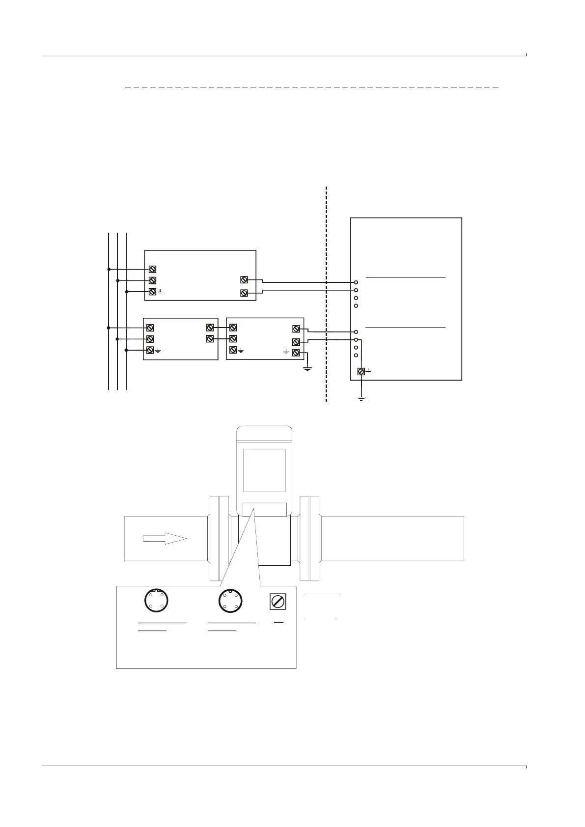
Fig. 78 Operation with safety barrier and external power supply
PE
L
N
PE
WARNING!
Incorrect cabling can cause the FLOWSIC500 to fail!
See Operating Instructions for further details!
Attention!
DO0 is optically insulated.
Do not use as HF output in battery powered mode!
Frequent activity results in a reduced battery life time.
[Ex ia]
EVC
intrinsically safe
DI+
DI-
NAMUR
[Ex ia]
FLOWSIC 500
intrinsically safe
Hazardous area
PE
M12 connector B-coded
2 + power supply
1 - power supply
3 - DO 1 (passive)
4 + DO 1 (passive)
Safe area
power
supply
U+
U-
L
N
L
N
[Ex ia]
safety
barrier
U+
U-
L N PE
M12 connector A-coded
1 + DO0 (NAMUR)
2 - DO0 (NAMUR)
3 n.c.
4 n.c.
M12connector
A-coded
1 + DO0 (NAMUR)
2 - DO0 (NAMUR)
3 n.c.
4 n.c.
For safety and entry parameters see
control drawing 9215965 for the USA and Canada
and control drawing 9215966 for the EU.
In the USA install in accordance with the NEC (ANSI/NFPA70),
in Canada install in accordance with CEC part 1,
in the EU install in accordance with EN 60079-14.
Further national regulations must be observed!
M12connector
B-coded
1 - power supply
2 + power supply
3 - DO 1 (passive)
4 + DO 1 (passive)
FLOWSIC500 with HF output powered with safety barrier and external power supply,
connected to electronic volume corrector
3
4
21
3
4
21
3
4
21