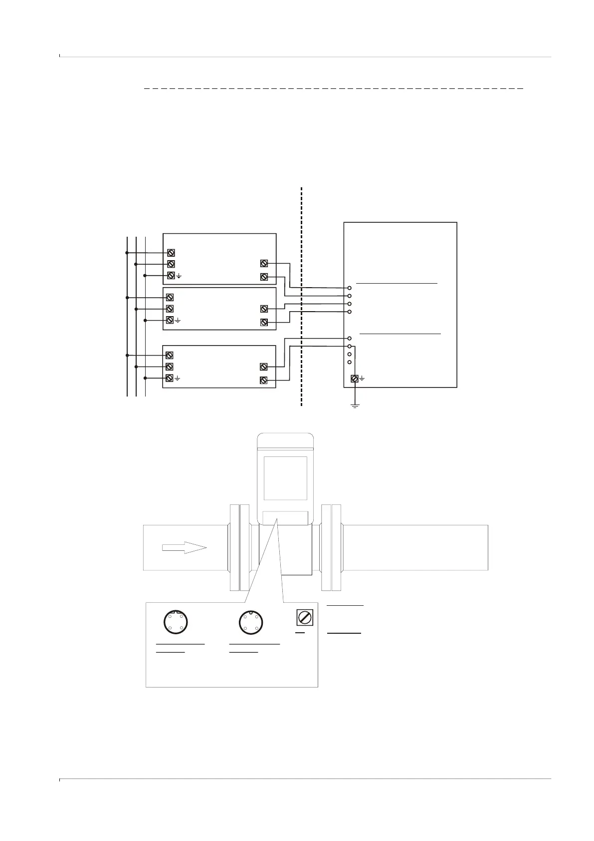
Fig. 79 Operation with external power supply (intrinsically safe)
For safety and entry parameters see
control drawing 9215965 for the USA and Canada
and control drawing 9215966 for the EU.
In the USA install in accordance with the NEC (ANSI/NFPA70),
in Canada install in accordance with CEC part 1,
in the EU install in accordance with EN 60079-14.
National regulations must be observed!
PE
WARNING!
Incorrect cabling can cause the FLOWSIC500 to fail!
See Operating Instructions for further details!
Attention!
RS485 must be powered externally!
For enviroments with relevant eletromagnetic disturbance
and long cables, shielded cables are recommend.
M12 connector
A-coded
1 + power supply
2 + data (RS485 A)
3 SRZHUVXSSO\
- data (RS485 B)
[Ex ia]
EVC
intrinsically safe
data+
data-
RS485
[Ex ia]
FLOWSIC500
intrinsically safe
Hazardous area
PE
M12 connector A-coded
2 + data (RS485)
- data (RS485)
1 + power supply
- power supply
M12 connector B-coded
2 + power supply
1 - power supply
3 - DO 1 (passive)
4 + DO 1 (passive)
Safe area
[Ex ia]
intrinsically safe
power supply
U+
U-
L
N
L
N
[Ex ia]
intrinsically safe
power supply
U+
U-
L
N
L N PE
M12connector
B-coded
1 - power supply
2 + power supply
3 - DO 1 (passive)
4 + DO 1 (passive)
FLOWSIC500 externally powered (IS) and connected to electronic volume corrector,
RS485 externally powered
3
4
21
3
4
21