Product description
FLOWSIC500 · Operating Instructions · 8025733/1GMJ/V4-2/2022-07 · © SICK Engineering GmbH 23
Subject to change without notice
2.4 Interfaces
The FLOWSIC500 supports various digital and serial interfaces.
The configuration of the interfaces as delivered is described in the delivery documents
provided with the respective device.
2.4.1 Pulse and status outputs
FLOWSIC500 has 4 digital switching outputs. Digital switching outputs DO_0, DO_2 and
DO_3 are electrically isolated according to EN 60947-5-6.
Alternatively, digital switching outputs DO_2 and DO_3 can also be configured as Open
Collector.
When used as pulse output, maximum 2 kHz can be output on digital switching output
DO_0 and maximum 100 Hz on digital switching outputs DO_2 and DO_3. When used as
status output, status information “Validity of measurement” or the result of the self-
diagnosis can be represented.
Digital switching output DO_1 is not electrically isolated. In normal mode, the diagnosis
warning is output on DO_1, test pulses are output in test mode.
The digital switching outputs are updated synchronously once per second.
2.4.2 Encoder totalizer
Alternatively, NAMUR switching output DO_0 can be configured so that the totalizer level of
the totalizer Vm, the meter state and a meter identification are output via asynchronous
serial communication. This allows the connection of volume converters with a suitable
input for encoder totalizers.
2.4.3 Serial data interface
The serial interface is designed as externally powered RS485 and requires an external
intrinsically safe power supply for operation.
Maximum cable length for the RS485 interface: 300 m
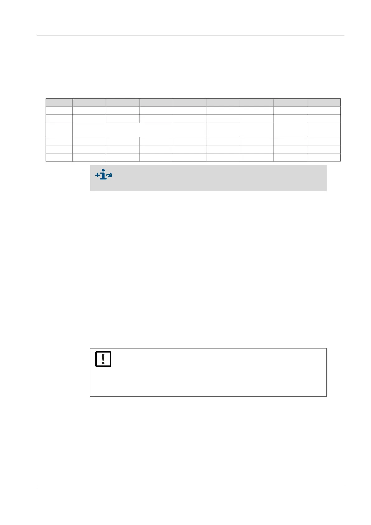
Table 1 Interface configurations
Type code I/O: F I/O: G I/O: H I/O: I or J I/O: K I/O: L I/O: M I/O: N
LF HF Encoder + LF RS485 Encoder + HF 2 x LF RS485 + HF RS485 + NF
DO_0 - HF pulses Encoder - Encoder - HF pulses -
DO_1 Normal operation: Diagnosis warning, test mode: Test
pulses
HF pulses As for config.
F, G, H, I, J
- -
DO_2 LF pulses - - - - LF pulses - NF pulses
DO_3 Malfunction Malfunction LF pulses - Malfunction LF pulses - -
Serial - - - RS485 - - RS485 RS485
● Information on explosion-technical characteristics and rated voltage
→ p. 46, §3.4.
● Details on standard interface configurations available → p. 51, §3.4.6.
NOTICE:
With encoder communication, it must be ensured that the transmitted digit
count or totalizer resolution can be processed by the connected volume
converter.
A parameter modification can be carried out on the FLOWSIC500 with the
FLOWgate
TM
operating software when the parameter locking switch is open.