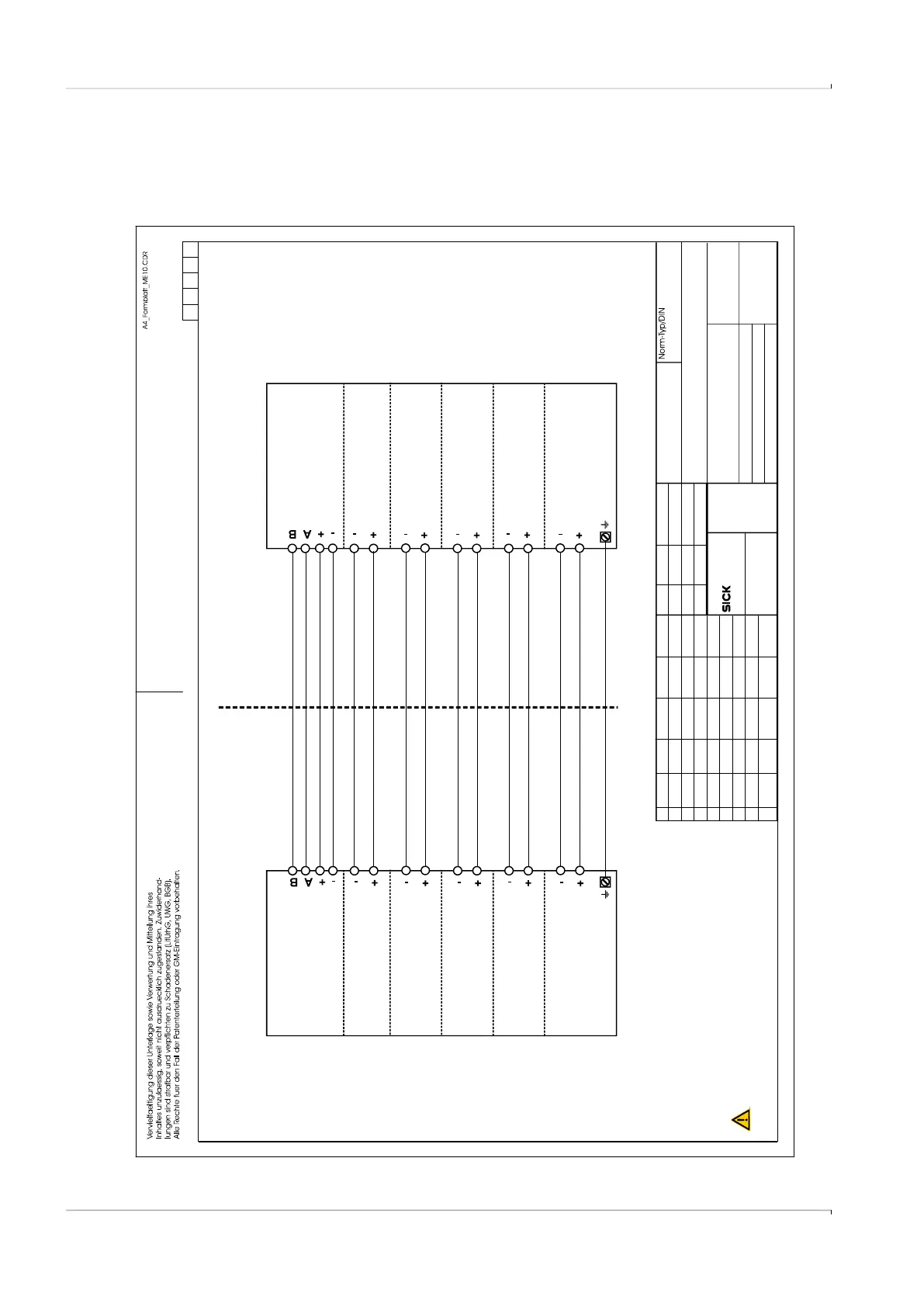
Fig. 80 Control diagram 9215965 (page 1)
SICK Engineering GmbH
Bergener Ring 27
01458 Ottendorf-Okrilla
Verteildatum:
Page
Ersatz für:
Änderung
gez.
Tag
Name
Ind.
Tag Name
Maßstab:
Werkstoff
Ersetzt durch:
Gepr.
Ursprung:
MKO
1of7
9215965
2014-07-16
Entity parameters of interconnected equipments must be complied as follows:
Uo < Ui, Io < Ii, Po< Pi, Co > Ci + Ccable, Lo > Li + Lcable
or Voc < Vmax, Isc < Imax, Ca > Ci + Ccable, La > Li + Lcable
Hazardous (classified) location
Non-hazardous location
Ui = 20 V
Ii = 667 mA
Pi = 772 mW
Ui=20V,Pi=1.1W
Uo = 8.2 V, Io = 0.83 mA
Po = 1.7 m W
Co = 7.6 μF, Lo = 100 mH
Ui = 20 V
Pi = 1. 1 W
Ui = 20 V
Pi = 1. 1 W
Ui = 20 V
Pi = 1.1 W
Ui = 20 V
Pi = 1. 1 W
Ci = 1.35 μF
Li = 0.03
FLOWSIC 500
BA T1
DO1
DO2
optical
isolated
DO3
optical
isolated
DO0
optical
isolated
RS485
(option)
optical
isolated
Uo or Voc <= 20 V
Io or Isc <= 667 mA
Po <= 772 mW
UoorVoc<=20V,Po<=1.1W
Ui or Vmax >= 8.2 V
Ii or Imax >= 0.83 mA
Ci + Ccable < 7.6 μF
Li + Lcable < 100 mH
Uo or Voc <= 20V
Po <= 1.1 W
Uo or Voc <= 20 V
Po <= 1.1 W
Uo or Voc <= 20 V
Po <= 1.1 W
Uo or Voc <= 20 V
Po <= 1.1 W
Co or Ca >= 1.35 μF + C
Lo or La >= 0.03 mH + Lcable
cable
Associated Equipment
Class I, Division 1, Groups C and D, Temp. Code T4
Ex ia IIB T4 Ga
ClassI,Zone0AExiaIIBT4Ga
.
-25°C < Tamb < 60°C
,
for extended range see Marking plate
.
In the US install in accordance with the NEC (NFPA70, Article 504)
and ANSI/ISA-RP12.06.01
In Canada install in accordance with CEC part 1
WARNING: EXPLOSION HAZARD
Substitution of components may impair Intrinsic safety
AVERTISSEMENT: La substituti on
de composants peut compromettre la securite intrinseque.
RISQUE D` EXPLOSION -
Exia Intrinsically Safe; Securite Intrinseque
For details see pages 2 of this drawing
Different parameters (values in brackets)
for circular connector options
must be observed, see page 3 - 6 also
kochami
kochami
kochami
draft
Ed.6
ZY57
01
02
03
2014-08-27
gepr.
kochami
2014-08-27
Control drawing FLOWSIC500 isolated I/O
2015-09-24
2018-05-02