150 FLOWSIC500 · Operating Instructions · 8025733/1GMJ/V4-2/2022-07 · © SICK Engineering GmbH
Annex
Subject to change without notice
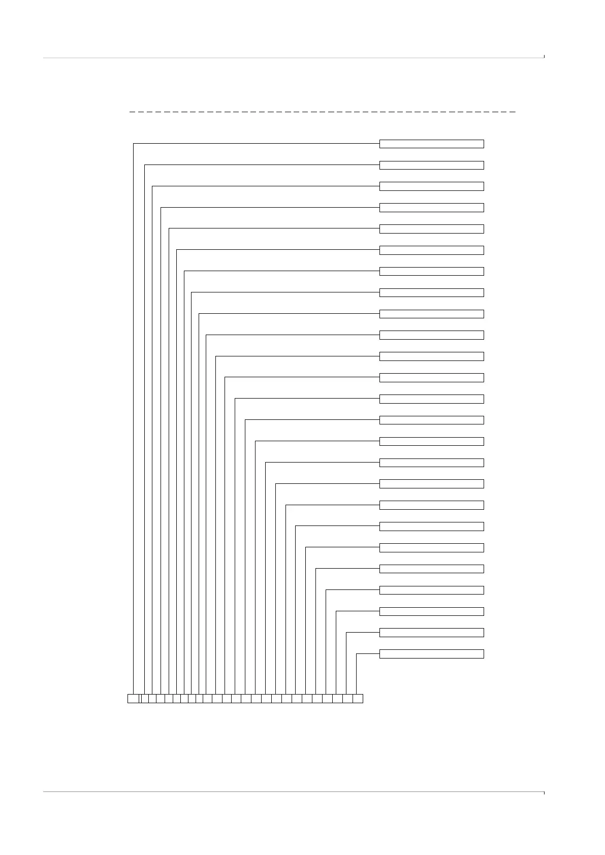
9.4 Type code
Fig. 67 Type code FLOWSIC500 (overview)
1
2
3
4
5
6
7
8
9
10
11
12
13
14
15
16
17
18
19
20
21
22
23
24
25
1
Measuring span
Flow direction
Transducer
Customized solution
14
21
22 EX certification
23 I/O (Interface configurations)
24 Conformity
18
Gas temperature / ambient temperature
Surface adapter / gas meter
8
19 Pressure range p-sensor
20 Cable connection
12 Nominal size gas meter
15 Maximum flow rate
16
17 Sensoric for volume correction
1
5 Mating surface
6 Connection p-sensor
7 Connection T-sensor
11 (Reserve)
XXF3
Material adapter/gas meter
9 Material certification adapter/gas meter
10
13 14 15
3 4 567
4 Pressure rating / flange standard
A2A1 1 X AA11A3BFL5
1 Device type
2
2
3
89101112
Flange-flange dimension adapter
25242322212019181716