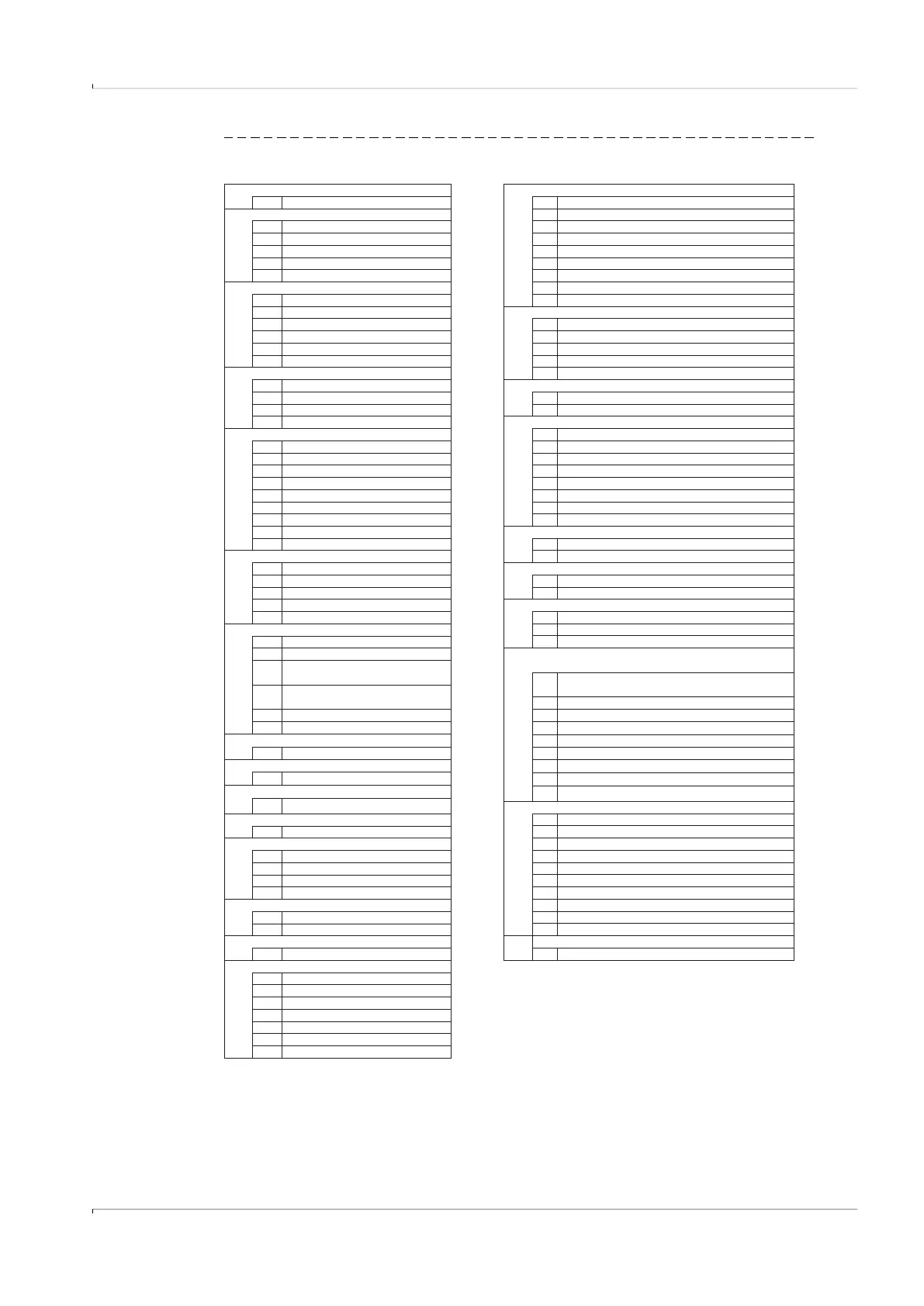
Fig. 68 Type code FLOWSIC500 (explanation)
FL5
FLOWSIC500 1
1:50
2
1:100
X
Replacement meter only 3
1:160
1
DN 50 / 2" 4
1:200
2
DN 80 / 3" 5
1:320
3
DN100 / 4" 6
1:400
D
DN150 / 6", adapter 4" 7
1:406
8
1:625
X
Replacement meter only
9 1:250
A
50 mm
B
171 mm A
-
E
241 mm B
T-Sensor external
G
300 mm
C T-Sensor internal
L
450 mm D
p/T-Sensoren external
E
p/T-Sensoren internal
1
PN16 / EN1092-1
2
Class 150 / ASME B16.5
1 -25°C ... +60°C / -25°C ... +60°C
3
PN16 / GOST 12815-80
3 -40°C ... +70°C / -40°C ... +70°C
4
PN16 / GOST 33259-2015
A-
X
Replacement meter only
B absolute 0.8 ... 5,2 bar
A
Flat face, smooth finish
C absolute 2.0 ... 10,0 bar
B
Raised face, smooth finish
D absolute 4.0 ... 20,0 bar
C
Form A / DIN EN 1092-1
E absolute 0.8 ... 20,0 bar
D
Form B1 / DIN EN 1092-1
F relative 0 ... 4.0 bar / 0 ... 58,0 PSI
E
GOST V1 Series 2
G relative 0 ... 10.0 bar / 0 ... 145.0 PSI
F
GOST V1 Series 1
H relative 0 ... 25.0 bar / 0 ... 362.6 PSI
G
GOST VB Series 1
H
GOST VB Series 2
1 2x M12 , 2x M8
3 2x M12
X Replacement meter only
1 Plug NPT 1/4"
B External with backup battery
2 Plug G1/4"
C Autarkic with battery pack (5 years)
3 Compression fitting 1/4"
4
Compression fitting D6
7
1 ATEX Zone 1 / IEC-Ex Zone 1, Group IIB
X Replacement meter only
2 ATEX Zone 1 / IEC-Ex Zone 1, Group IIC
A
without
3 CSA Class 1 Div 1, Group CD
B
2xG1/2" 1x temperature pocket (left-
right), 1x blind plug
23
C
2xG1/2" 1x temperature pocket (right-
left), 1x blind plug
F Impulse LF + Status (galvanically isolated)
D
2xG1/2" 2x temperature pocket
G Impulse HF + Status (galvanically isolated)
E 2x G 1/2" plug
H Encoder + Impulse LF (galvanically isolated)
8
I
RS485 Module - battery powered (external)
1
Aluminum / aluminum
J RS485 Module - line powered (external)
K Encoder + Impulse HF (not galvanically isolated)
A
3.1 / 3.1
L 2 x LF-Impulses (galvanically isolated)
M RS485 Module - line powered (external) + Impulse HF
1
Shot-peened / SICK standard
N RS485 Module - line powered (external) + Impulse LF
X
-
2 PED
3 MID, PED
1 DN 50 / 2"
4 PED, CIS
2 DN 80 / 3"
6 PED, China
3 DN100 / 4"
7 PED, Ukraine
C
DN150 / 6"
8 PED, India
9 PED, TR CU
A Left - right
A Customized
B
Right - left
B Customized
C Customized
1
Type 1: 300 kHz
XX -
A Qmax 65 m³/h
B
Qmax 100 m³/h
C
Qmax 160 m³/h
D
Qmax 250 m³/h
E
Qmax 400 m³/h
F
Qmax 650 m³/h
G
Qmax 1000 m³/h
Measuring span
Connection T-sensor
Flow direction
Transducer
Maximum flow rate
Reserve
Surface adapter/gas meter
Material adapter/gas meter
Material certification adapter/gas meter
Nominal size gas meter
Customized solution
1
2
3
4
6
5
I/O (Interface configurations)
EX certification
Power supply
Conformity
Sensoric for volume correction
Gas temperature/ambient temperature
Pressure range p-Sensor
Cable connection
Nominal size adapter
19
17
18
22
21
14
15
16
9
10
11
12
13
20
24
25
Mating surface
Connection p-sensor
Device type
Flange-flange dimension adapter
Pressure rating / flange standard