Maintenance and meter exchange
FLOWSIC500 · Operating Instructions · 8025733/1GMJ/V4-2/2022-07 · © SICK Engineering GmbH 117
Subject to change without notice
7.4.7 Disconnecting electrical connections
Observe the safety information in §3.4 (→ p. 46)!
Depending on the configuration of your FLOWSIC500, proceed as follows:
1 Disconnect the potential equalization line at the outer ground terminal (on the right of
the M12 plug-in connections) of the electronic housing (→ Fig. 18, p. 50).
2 If installed, remove the plug-in connector cover. To do so, loosen the capstan screws
(→ Fig. 29, p. 60).
3 If installed, manually loosen and remove the M12 plug-in connectors for external power
supply and the signal output (→ Fig. 18, p. 50).
4 If installed, manually loosen and remove the plug-in connectors of the pressure and
temperature sensors ( → Fig. 18, p. 50).
5 Open the electronics cover (→ p. 48, §3.4.3).
▸
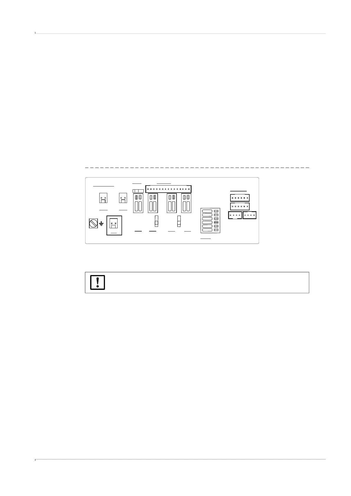
Configuration with external power supply and backup battery:
Switch the backup battery to “N.c.”.
Fig. 54 Switching the backup battery
▸
Self-sufficient power configuration with battery packs:
Remove the battery packs and dispose of or store properly according to → p. 108,
§7.1.
6 Close the electronics cover again (→ p. 48, §3.4.3).
EXT. POWER
BAT1
N.c.
DO3
DO0
+-
RS485
*
-
+
-
+
A
B
P1
P2
T1
T2
SENSORS
DISPLAY
LOCK
OFF ON
5..12V
NAMUR
4,5..16V
1.5 mm²
(AWG 16)
W
R :100
S
2..16V
2..16V
4074419
DO2
*Optional
V see module
CC
.
OC NAM
UR
2..16V
DO1
+-
BAT2
+-
+-
OC NAM
UR
+- +-
SICK recommends inserting new batteries during every meter exchange.