34 FLOWSIC500 · Operating Instructions · 8025733/1GMJ/V4-2/2022-07 · © SICK Engineering GmbH
Product description
Subject to change without notice
2.9 Sealing
The FLOWSIC500 is secured at the factory with a seal on the cover.
Gas flow meter and adapter can be secured at the joint by a user seal (adhesive label)
glued with approximately equal spread on gas flow meter and adapter.
Optionally, the electronics cover can also be protected by the customer after the end of the
installation against unauthorized opening.
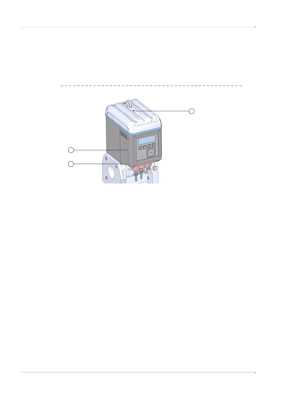
Fig. 8 Factory seal of the cover on the gas flow meter
In addition, the FLOWSIC500 has seal positions on the terminal compartment cover and
the plug-in connector cover.
An adhesive label secures the interfaces and the parameter lock by the terminal cover
compartment.
During commissioning, the plug-in connector cover must be secured according to national
regulations. This can be performed with an adhesive label which is glued with
approximately equal spread on the cover and the enclosure or alternatively by using
capstan screws and a tensioned sealing wire and a wire seal.
1 Seal position
2 Possible position of the adapter seal
3 Possible position of the electronic cover seal
1
2
3