Product description
FLOWSIC500 · Operating Instructions · 8025733/1GMJ/V4-2/2022-07 · © SICK Engineering GmbH 19
Subject to change without notice
2.2 System components
The FLOWSIC500 measuring system comprises:
● FLOWSIC500 gas flow meter,
● Adapter for installation in pipeline and
● Optional p&t sensors for the volume conversion device option.
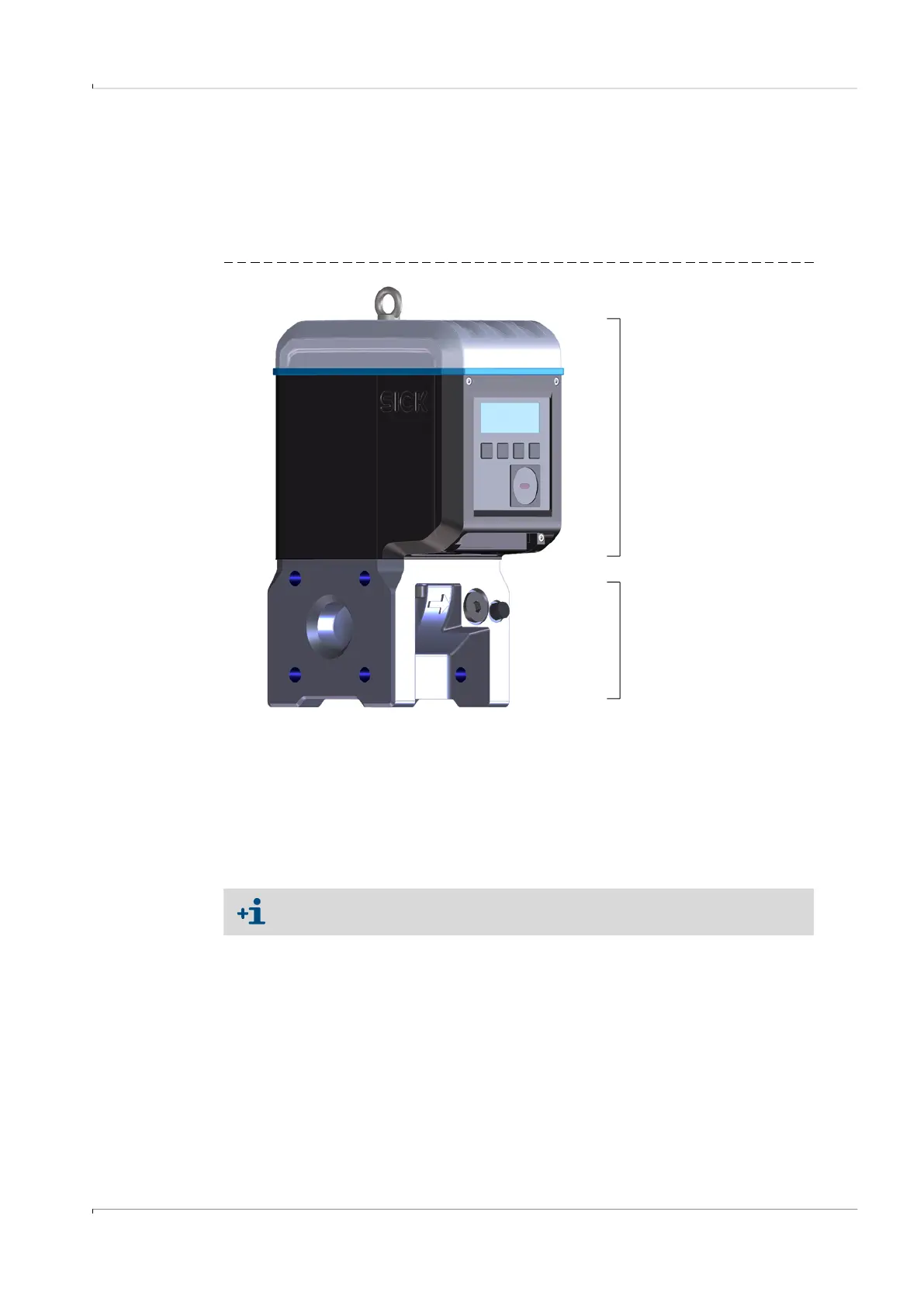
Fig. 3 FLOWSIC500 components
2.2.1
Adapter
The meter body is available in various flange standards and fitting lengths to connect the
gas flow meter to the system pipeline.
Depending on the version, the adapter is designed for assembly on line flanges PN16 in
accordance with DIN EN1092-1, CL150 in accordance with ASME B16.5, or 1.6MPa in
accordance with GOST 12815-80.
Gas flow meter
Adapter
Fitting lengths available: → p. 155, §9.6.