EasyManuals Logo

SICK FLOWSIC500 User Manual

SICK FLOWSIC500
176 pages
To Next Page IconTo Next Page
To Previous Page IconTo Previous Page
Page #62 background imageLoading...
Page #62 background image
62 FLOWSIC500 · Operating Instructions · 8025733/1GMJ/V4-2/2022-07 · © SICK Engineering GmbH
Installation
Subject to change without notice
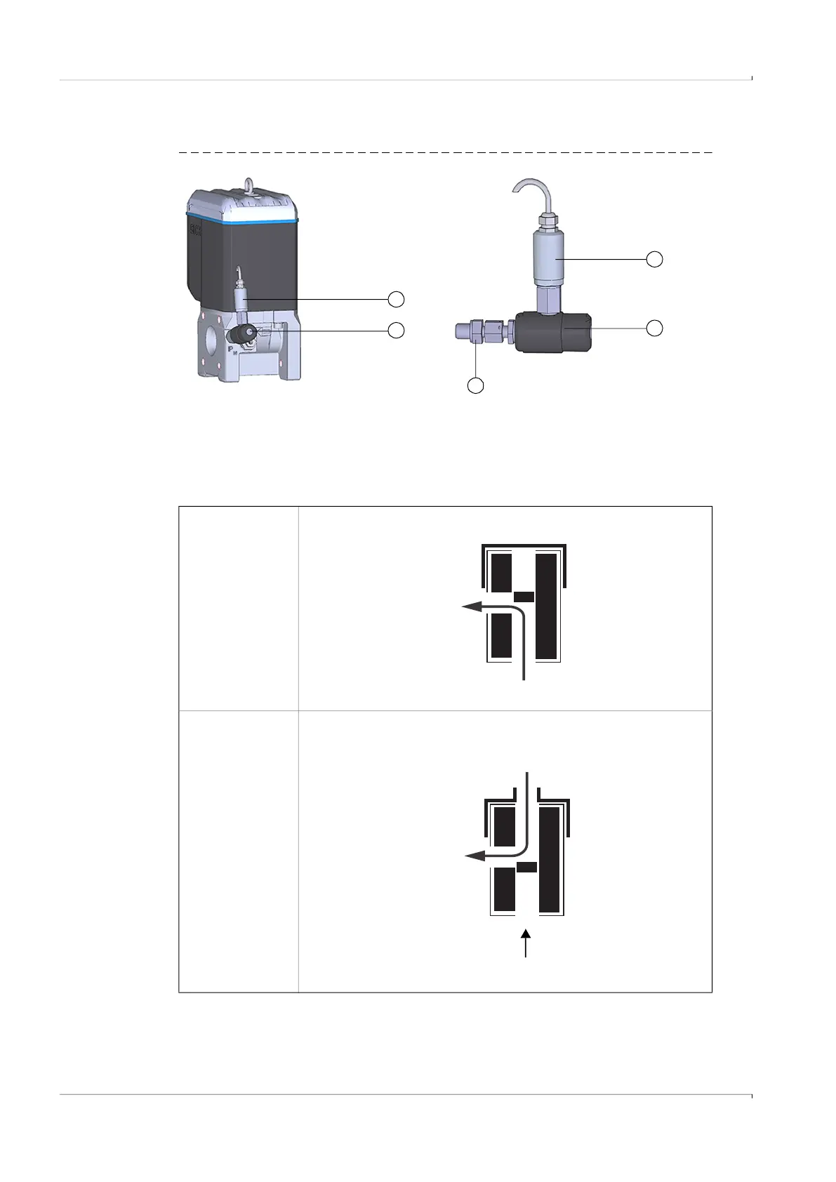
4 Fit the pressure sensor on the test valve BDA04 (→ Fig. 31).
Fig. 31 Test valve BDA04 with pressure sensor fitted
Table 20 Test valve BDA04 positions
1 Pressure sensor, connection thread G 1/4“
2 Test valve BDA04
3 FLOWSIC500 connection (G 1/4“ male thread)
1
2
2
1
3
Measuring
position
Test position
FLOWSIC500
Pressure sensor
FLOWSIC500
Test pressure
Pressure sensor

Table of Contents

Questions and Answers:

Question and Answer IconNeed help?

Do you have a question about the SICK FLOWSIC500 and is the answer not in the manual?

SICK FLOWSIC500 Specifications

General IconGeneral
BrandSICK
ModelFLOWSIC500
CategoryMeasuring Instruments
LanguageEnglish

Related product manuals