Installation
FLOWSIC500 · Operating Instructions · 8025733/1GMJ/V4-2/2022-07 · © SICK Engineering GmbH 63
Subject to change without notice
Variant 2: Installation with three-way test valve (to -40 °C)
Here, a conventional three-way test valve is used.
Install the three-way test valve with pressure sensor fitted at a suitable location next to the
FLOWSIC500. A pressure line serves to connect the pressure measuring connection of the
FLOWSIC500 to the three-way test valve.
Two variants of the pressure connection set with three-way test valve are available. The
type code indicates which variant must be selected.
▸
Check type code, position 6 “p-sensor connection”, on the type plate (→ Fig. 1) of your
FLOWSIC500.
▸
Select the connection set suitable for the pressure connection on the FLOWSIC500,
→ p. 136, §8.1.
▸
For the complete type code description, see → p. 150, §9.4.
Fig. 32 Pressure connection on FLOWSIC500
1 Fasten the three-way test valve at a suitable location.
1 Remove the dummy plug on the pressure measuring port marked “P
m
”.
2 When the meter body has an NPT 1/4“ thread, first screw in the adapter from NPT 1/4"
to G 1/4" (Part No. 2075562).
3 Screw in the pipe screw fitting for pipe 1/4" or pipe D6.
4 Install the pressure line between the FLOWSIC500 and the three-way test valve.
5 Fit the pressure sensor to the three-way test valve.
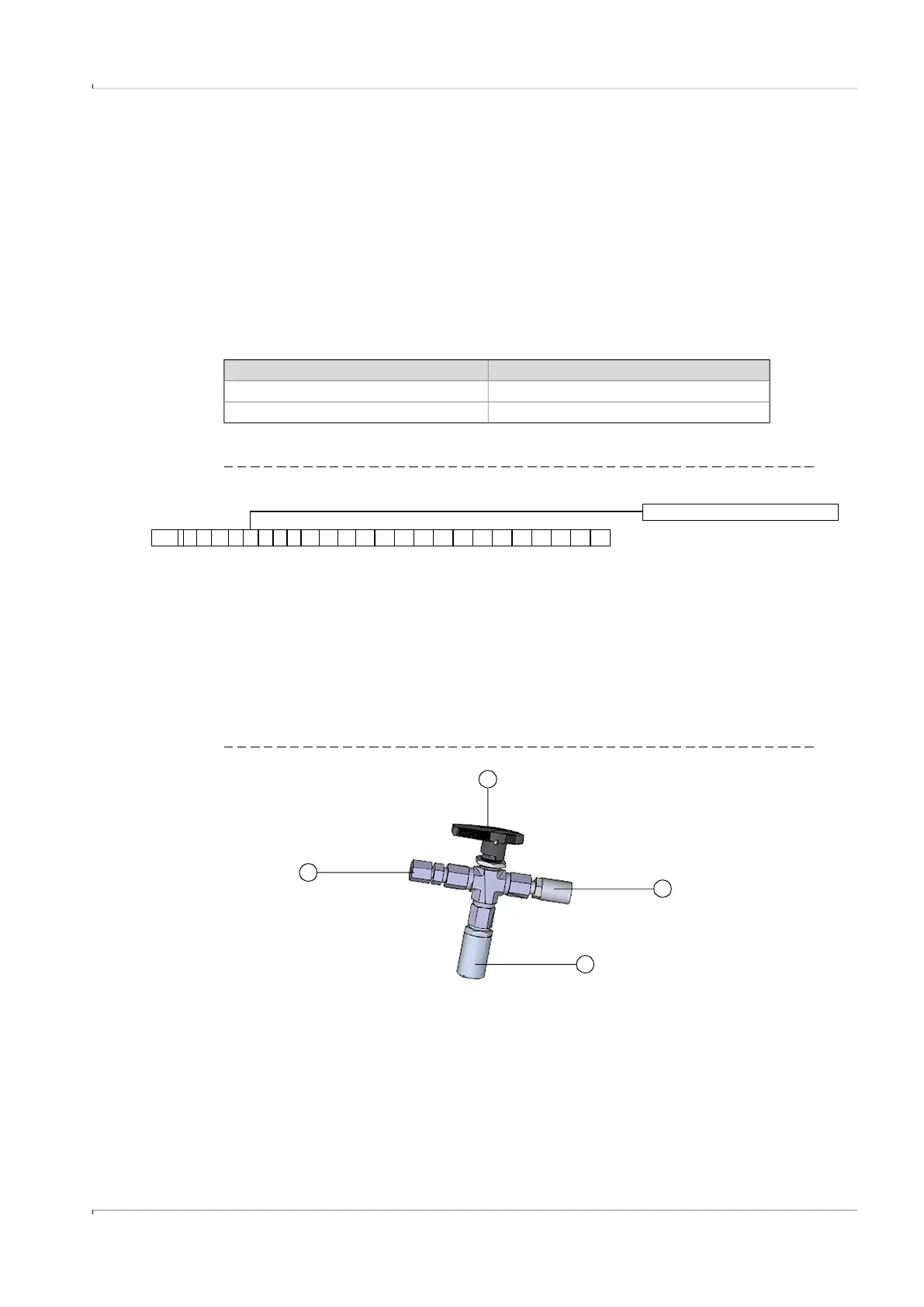
Fig. 33 Pressure sensor installation on the three-way test valve (-40 °C)
“Connection p-sensor” in type code Pressure connection
3 Pipe screw fitting pipe 1/4"
4 Pipe screw fitting pipe D6
1
6 Connection p-sensor
FL5 2
23 4 56
1878910111213 14 15 16 17 2519 20 21 22 23 24
1
2
3
4
1 Pipe screw fitting 1/4“ NPT on pipe D06
or pipe screw fitting 1/4“ NPT on pipe 1/4
"
2 Hand lever
3 Test connection (Minimess coupling)
4 Pressure sensor, connection thread G 1/4
"