64 FLOWSIC500 · Operating Instructions · 8025733/1GMJ/V4-2/2022-07 · © SICK Engineering GmbH
Installation
Subject to change without notice
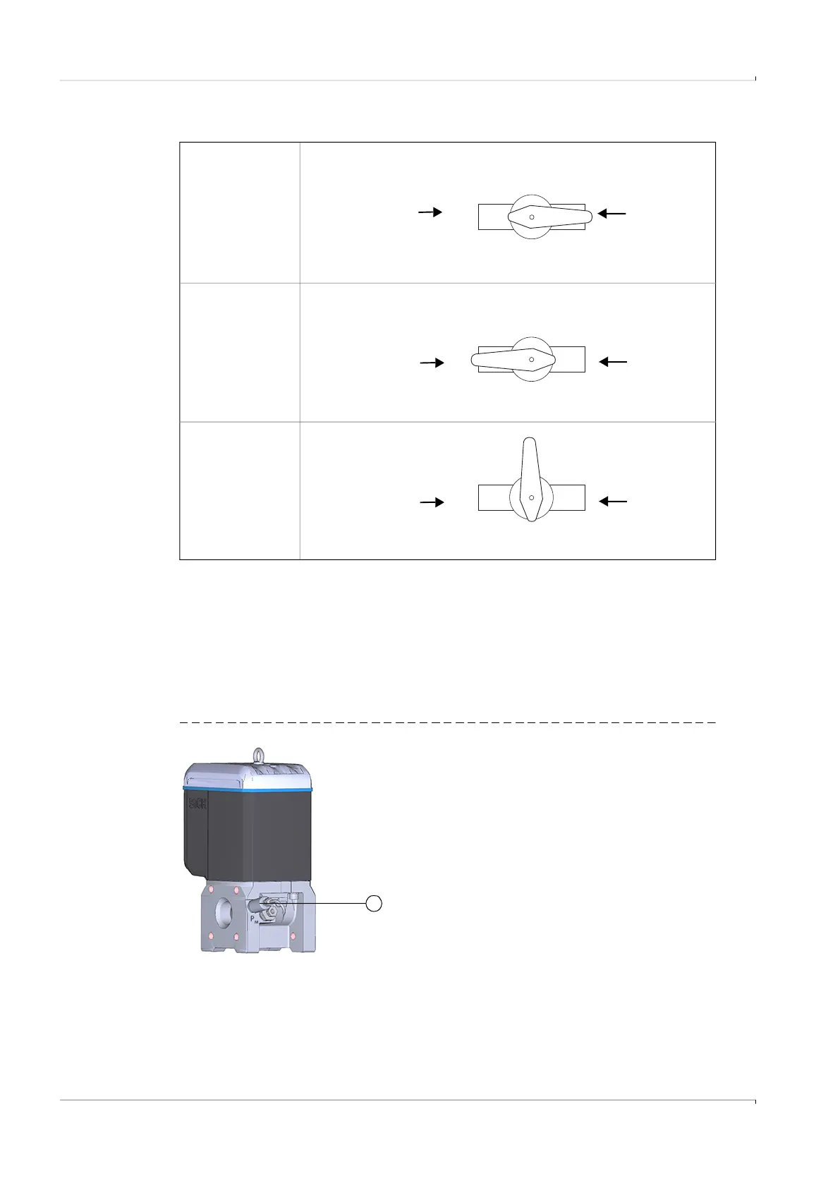
Table 21 Three-way test valve positions
Variant 3: Installation without a three-way test valve
Here, the pressure sensor is connected directly to the FLOWSIC500.
1 Remove the dummy plug on the pressure measuring port marked “P
m
”.
2 When the meter body has an NPT 1/4“ thread, first screw in the adapter (Part No.
2075562).
3 Fit the pressure sensor.
Fig. 34 Installation without three-way test valve
Measuring
position
Test position
Closed position
Test pressure
FLOWSIC500
Test pressure
FLOWSIC500
Test pressure
FLOWSIC500
1 Pressure sensor, connection thread G 1/4“
1