Maintenance and meter exchange
FLOWSIC500 · Operating Instructions · 8025733/1GMJ/V4-2/2022-07 · © SICK Engineering GmbH 125
Subject to change without notice
7.4.10.1 Leak tightness check successful
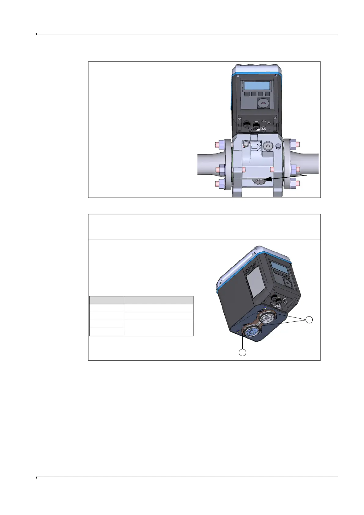
7.4.10.2 Leak tightness check not successful
1 Remove the test cap with the socket
wrench.
2 Screw in the closure cap.
3 Then connect the replacement gas
flow meter to the electric system, see
§3. 4 “Electrical installation”.
1 Close the line and depressurize the device.
2 Vent the environment.
3 Remove the gas flow meter from the adapter as described, see → p. 118, §7.4.8.
4 Check flat seal (1) and the O-rings on
connections pieces (2) for
completeness, intactness and
correct installation. When the sealing
elements are damaged, a new seal
set is available as spare part.
1
2
Meter size Item number
DN50 2067394
DN80 2067395
DN100
2067396
DN150