44 FLOWSIC500 · Operating Instructions · 8025733/1GMJ/V4-2/2022-07 · © SICK Engineering GmbH
Installation
Subject to change without notice
3.3.3.1 Assembly clearances
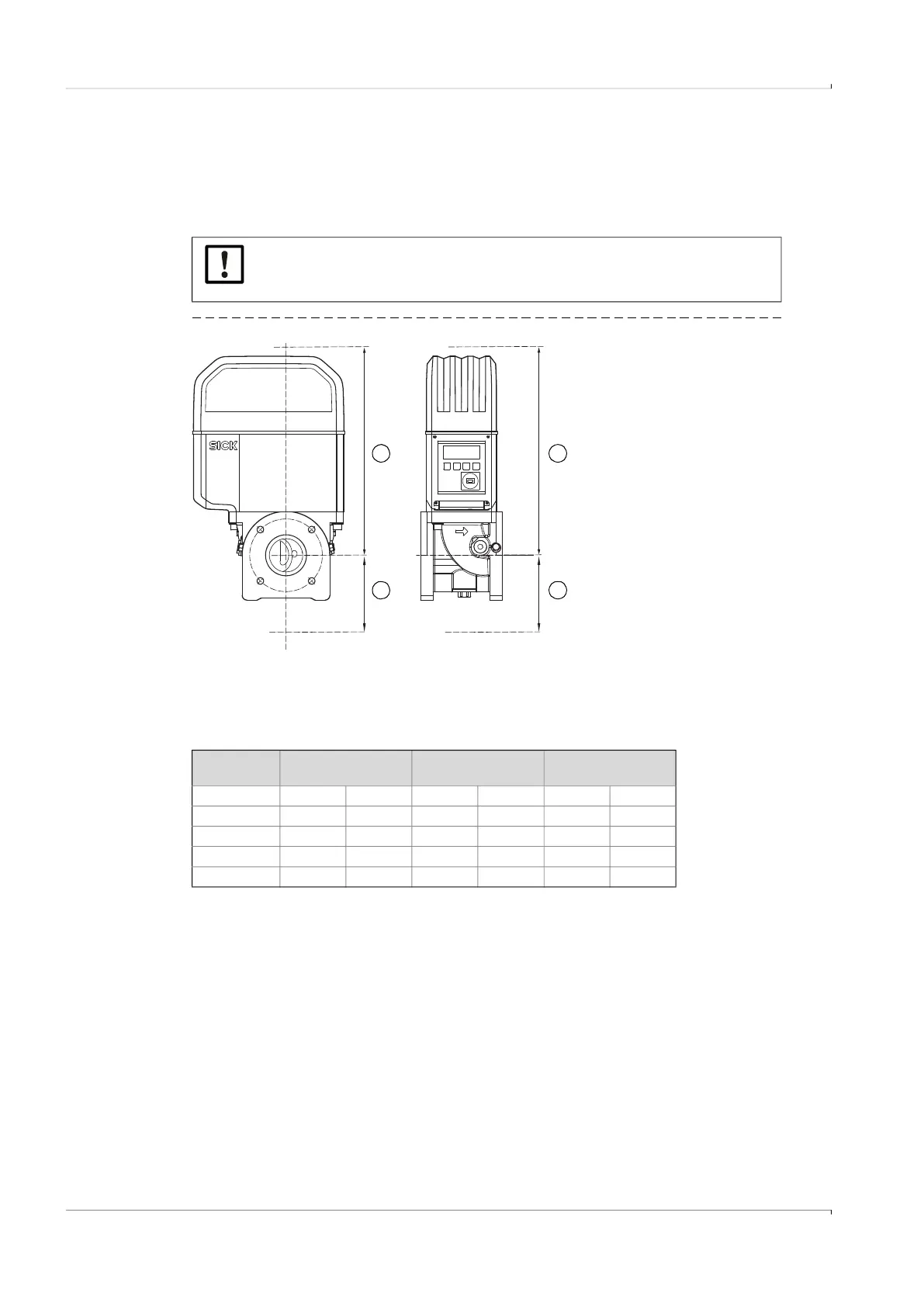
Maintain adequate assembly clearances to ensure there is enough room to exchange the
gas flow meter. The upward clearance is needed to remove the gas flow meter from the
adapter and to put it back on again. The downward clearance is needed to loosen the
screws, take these out or insert these again and to fit the tool correctly.
Fig. 14 Assembly clearances
Table 12 Minimum clearance required starting from the pipe axis
NOTICE:
Depending on the tool used and the installation location, adequate clearances
to the sides are also required.
1
1
2
2
1 Upward clearance
2 Downward clearance
Meter size Upward clearance,
without lifting lug
Upward clearance,
with lifting lug
Downward clearance
[mm] [in] [mm] [in] [mm] [in]
DN50/2" 300 11,81 340 13,39 200 7,87
DN80/3" 460 18,11 510 20,08 250 9,84
DN100/4" 520 20,47 570 22,44 320 12,6
DN150/6" 520 20,47 570 22,44 320 12,6