Installation
FLOWSIC500 · Operating Instructions · 8025733/1GMJ/V4-2/2022-07 · © SICK Engineering GmbH 45
Subject to change without notice
3.3.3.2 Pipeline torque
Table 13 Pipeline torque
3.3.3.3
Installation in pipeline
1 Select suitable bolts.
Recommended bolts → Table 8.
2 Use the hoisting equipment to position the FLOWSIC500 in the desired location in the
pipeline.
Lay the pipelines without tension to the device to be installed!
3 Insert and align the gaskets.
4 Apply lubricant to the bolts.
5 First screw the bolts by hand into the adapter to the stop.
– Screw in the bolts according to DIN835 with the shorter thread end.
– The bolts according to ASME B18.31.2 can be screwed in with any end.
6 Check the thread length in the adapter is fully utilized.
7 Then install the washers and nuts, and tighten them by hand.
8 Check whether the thread length of the nut is fully utilized.
If necessary, use a different bolt length.
9 Check correct positioning of flange gaskets.
10 Tighten nuts evenly and crosswise in small steps until the specified tightening torque is
reached (→ Table 8).
Make sure the flange sits free of tension.
11 Slowly increase the pressure in the pipeline.
Gradient: Max. 3 bar/min (45 psi/min)
12 Carry out a leak tightness check on the pipeline (in accordance with the pipeline
operating company's specifications).
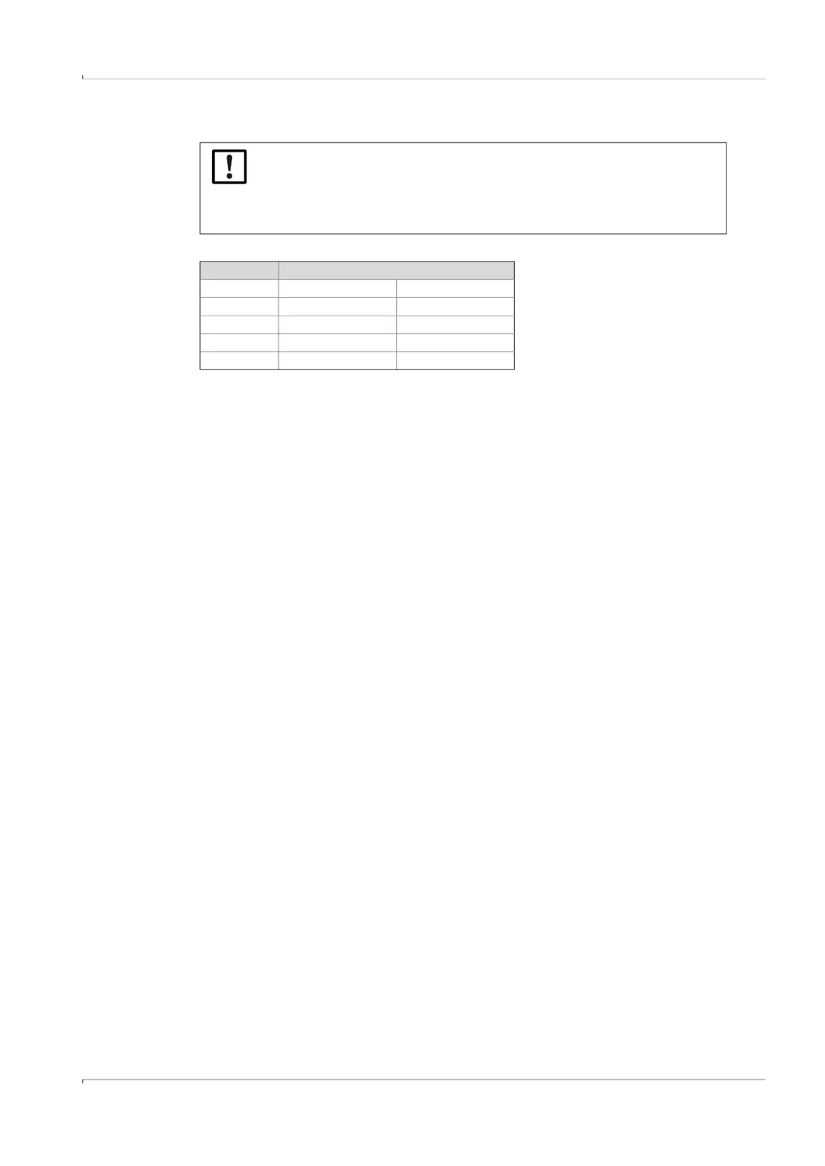
NOTICE:
If the FLOWSIC500 is installed so that the gas flow meter projects sideways
from the pipeline, the gas flow meter weight creates a torque on the pipeline.
▸
Make sure the pipeline is capable of holding the gas flow meter → p. 45,
Table 13.
Meter size Torque
[Nm] [lbf ft]
DN50/2" 6 5
DN80/3" 16 12
DN100/4" 31 23
DN150/6" 31 23