Here you will nd an overview of the signals for drive functions at the X5 and X6 slots, see section
Digital input signals, Table 4-2 (Page 132).
You can nd information on safe digital control Door OPEN/CLOSE with emergency stop via 3
digital inputs in the section Concept of safe digital control of Door OPEN/CLOSE with emergency
stop via 3 digital inputs.
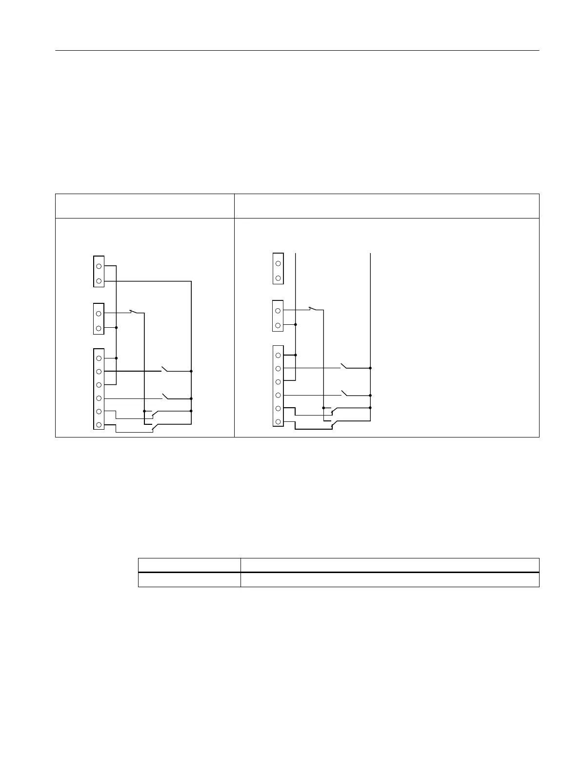
Table 5-4 Terminal circuit diagrams for emergency stop with 3 digital inputs
Connection to an internal 24 V control volt‐
age
Connection to an external control voltage
;
;
,Q
8
RXW
9
$
,Q
,Q
,Q
,Q
ದ
ದ
ದ
,Q
,Q
,Q
,Q
,Q
;
;
ದ
;
;
8
RXW
9
$
,Q
,Q
,Q
,Q
,Q
ದ
ದ
ದ
'&,1387
0,19P$
0$;9P$
,Q
,Q
,Q
,Q
,Q
Congurable via the service menu "General setup > Special parameters > FBLOCK conguration > FBLOCK Cong. Emergency
stop 3 inp."
In 0: Emergency stop device
In 1: Wiring depends on the sensor type and the conguration of Input 1.
5.4.2 Voltage output
Slot X4 Function
DC OUTPUT 24 V ±15 %, max. 400 mA
Controllers
5.4 Connecting terminals
ATD4xxW for industrial applications
System Manual, 06/2022, A5E51901827B AA 135

 Loading...


