5.7 Sensors and external sensor interface module
5.7.1 Overview
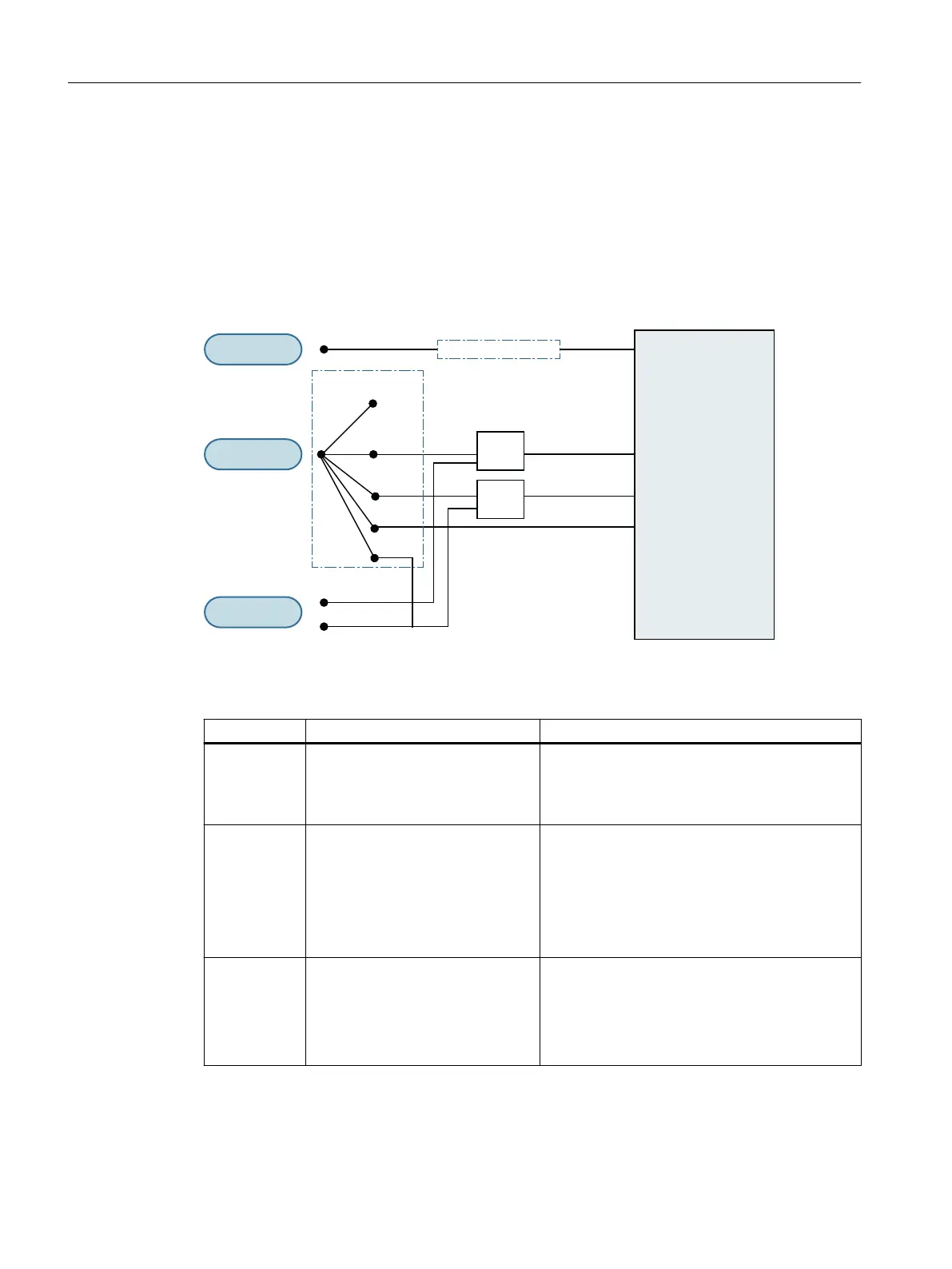
The signals in the gure below are processed and generated via the internal signal logic of
SIDOOR ATD4xxW controllers. The system reaction to the displayed signals is described in the
section Optional safety settings (Page 112).
Interne
Sensorlogik
3UR]HVVDEELOG
%:6
65
'&236
'&236
/%
S %:665
S
ุ
ุ
7HVW287
LQDFWLYH
,QSXW
2XWSXW&OV
/%
Figure 5-5 Sensor signals
Table 5-26 Sensor signals
Signal Meaning Source
DCOPS Door Closed / Opened Position Sen‐
sor
(Door Closed / Opened Position Sen‐
sor)
Signal can be transferred locally (terminal X6, "In‐
put1") and/or via the process image (for more, see
table DCMD extension bits (Page 320))
LB Light barrier
(Light barrier)
Signal is only contained in the process image
(see DCMD extension bits (Page 320)).
As of V1.14: Signal can be transferred locally (ter‐
minal X6, "input1") and / or via the process image
(for more information, see the table DCMD exten‐
sion bits (Page 320)). 0-active local signal without
function test.
TestOUT Function test signal Signal is automatically output by the controller via
a digital relay output.
• Relay module terminal X12 (reversing relay)
• Fieldbus module terminal X100.1, X100.2
(closed relay)
Controllers
5.7 Sensors and external sensor interface module
ATD4xxW for industrial applications
166 System Manual, 06/2022, A5E51901827B AA

 Loading...


