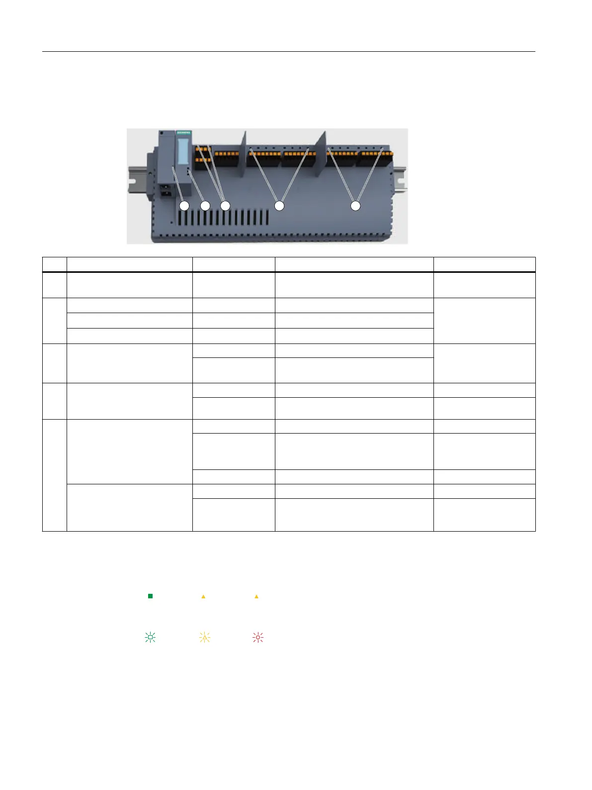
LEDs of the Compact Field Unit
The following LEDs are located on the front of the CFU.
Identification Color Meaning Brief description
① LK1 and LK2 Green LED for status display on the BusA‐
dapter
Connection status
②
● PWR
Green Power supply (Power) Diagnostics of the CFU
(LEDs on the interface
dome)
● RN
Green Operating mode (RUN)
● ER/MT
Red/yellow Error indication (Error/Maintenance)
③ PS1 and PS2 Green Supply voltage PS <x> is available Power supply
Red Problem with supply voltage PS <x>
(missing or faulty)
④ DIQ0 to DIQ7
LED display on channel
(DIQ<n>)
Green or OFF Signal status 1 or 0 Signal OK
Red Error display (Error) Error
⑤ For CFU PA:
FB0 to FB7
LED display on fieldbus con‐
nection (FB<n>)
Green Field device connected and OK Field device connected
Yellow Status display (Maintenance) Maintenance deman‐
ded or maintenance re‐
quired
Red Error display (Error) Error
For CFU DIQ:
DIQ8 to DIQ15
LED display at channel
(DIQ<n>)
Green or OFF Signal status 1 or 0 Signal OK
Red Error display (Error) Error
Table 9-1 Legend for the following tables:
ON LED lit
Off Off LED not lit
* * * * Any status (not relevant)
Flashes Maintenance status (flashes)
Diagnostics of the CFU
9.2 Diagnostics via LED displays
SIMATIC CFU
108 Commissioning Manual, 08/2019, A5E39252870-AD