See also
Use in hazardous areas (Page 29)
Installing the CFU (Page 50)
11.3.2.6 Connecting the cables
All cables on the housing must be effectively clamped to prevent dragging or twisting.
Cable and conductor glands
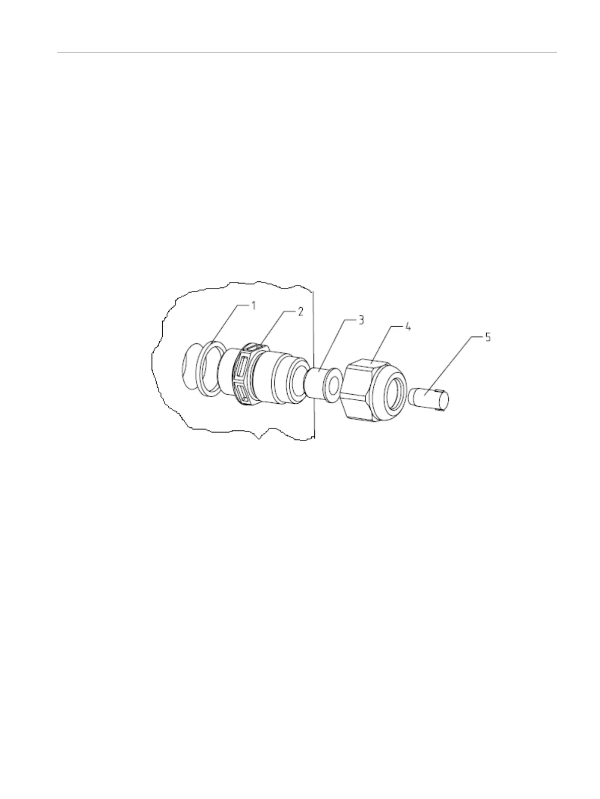
Upon delivery of the SIMATIC CFU with aluminum housing, all cable and conductor glands with
the components shown in the figure are present.
Configuration of cable and conductor glands upon delivery
No. Component of the cable and conductor gland Configuration
without cable 4-8 mm cable 7-13 mm cable
1 Housing sealing remains remains remains
2 Body (thread M20x1.5) remains remains remains
3 Reducing insert remains remains remove
4 Cap nut remains remains remains
5 Dummy plugs remains remove remove
Depending on the application, you may need to remove or reinstall the reducing insert and/or
the blanking plugs. Whenever possible, set aside any components that you have removed so
that you can use them again if the configuration changes.
It is possible to install specially certified cable and conductor glands, as well as blanking and
sealing plugs in the aluminum housing.
Compact Field Unit in the housing for use in a hazardous area
11.3 Configuration with SIMATIC CFU with aluminum housing
SIMATIC CFU
Commissioning Manual, 08/2019, A5E39252870-AD 139