A.3 CFU DIQ: Terminal assignment
You configure the connections of the Compact Field Unit DIQ in HW Config.
Pin assignment
You can find additional information in section "Connecting the power supply to the CFU
(Page 56)".
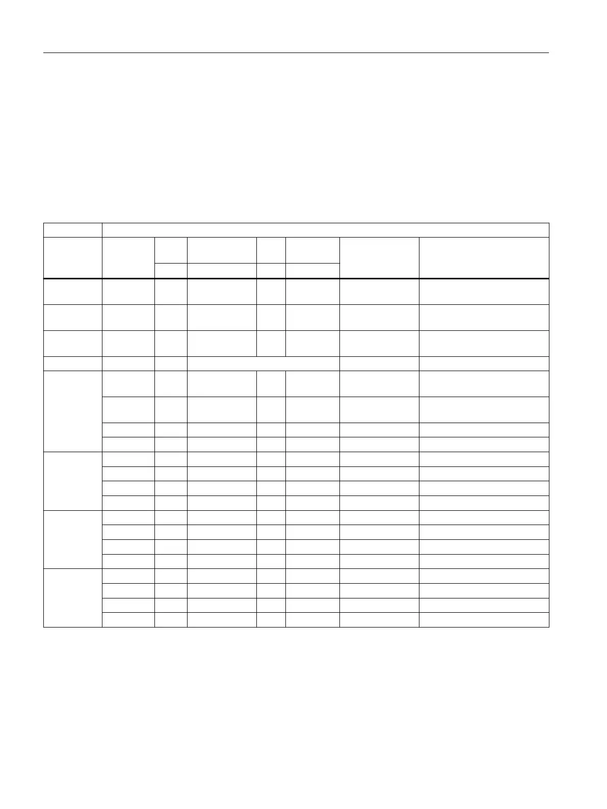
Table A-8 Pin assignment of the inputs / outputs of the CFU DIQ
Pin assignment
Area / Plug Connec‐
tion
Plug Identification Plug Identifica‐
tion
Allocation Explanations
Pin Pin
BusAdap‐
ter / X5
X5 BusAdapter
DC
24V / X80
PS1 1 1L+ 2 1M Supply voltage 1
DC
24V / X81
PS2 1 2L+ 2 2M Supply voltage 2
GND / X82 Ground 1-6 3M; 4M; 5M; 6M; 7M; 8M 6 terminals for ground (M)
DIQ / X10 DIQ0 1 0+ 2 0- Channel 0 (DIQ0) (counter,
frequency measurement)
DIQ1 3 1+ 4 1- Channel 1 (DIQ1) (counter,
frequency measurement)
DIQ2 5 2+ 6 2- Channel 2 (DIQ2)
DIQ3 7 3+ 8 3- Channel 3 (DIQ3)
DIQ / X11 DIQ4 1 4+ 2 4- Channel 4 (DIQ4)
DIQ5 3 5+ 4 5- Channel 5 (DIQ5)
DIQ6 5 6+ 6 6- Channel 6 (DIQ6)
DIQ7 7 7+ 8 7- Channel 7 (DIQ7)
DIQ / X12 DIQ8 1 0+ 2 0- Channel 8 (DIQ8)
DIQ9 3 1+ 4 1- Channel 9 (DIQ9)
DIQ10 5 2+ 6 2- Channel 10 (DIQ10)
DIQ11 7 3+ 8 3- Channel 11 (DIQ11)
DIQ / X13 DIQ12 1 4+ 2 4- Channel 12 (DIQ12)
DIQ13 3 5+ 4 5- Channel 13 (DIQ13)
DIQ14 5 6+ 6 6- Channel 14 (DIQ14)
DIQ15 7 7+ 8 7- Channel 15 (DIQ15)
Appendix
A.3 CFU DIQ: Terminal assignment
SIMATIC CFU
184 Commissioning Manual, 08/2019, A5E39252870-AD