11.3.2.7 CFU PA in aluminum housing: Connecting the field bus
Introduction
The PROFIBUS PA cables are introduced into the housing by means of cable glands.
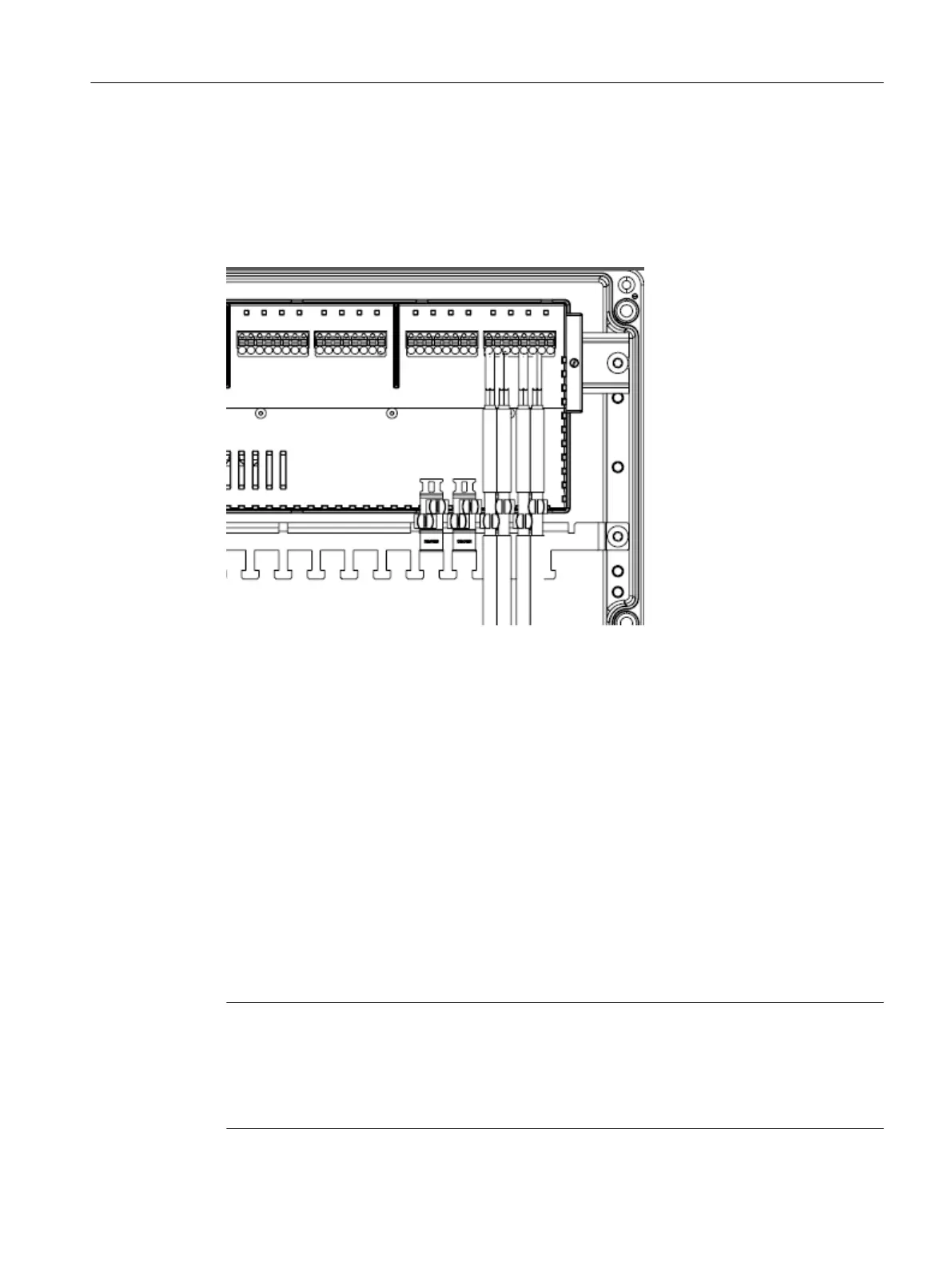
Figure 11-3 Connecting the field devices: Spur lines on FB0 to FB7
Basic procedure
You can find information on this in the section "CFU PA: Connecting a PROFIBUS PA field
device (Page 59)".
1. Preparing the cables (Page 63)
2. Connecting the cables
– Opening the housing
– Connecting spur lines to the terminal block (Page 62)
– Connecting cable shields (Page 142)
3. Closing the housing
4. Ensure that there is an appropriate strain relief for the cables outside the housing. Even
when installed in the housing, the cable glands do not serve as strain relief.
Note
Secure fieldbus cable with screw terminals (according to approval)
When screw terminals are used to secure the fieldbus cables, the following wiring direction
must be adhered to:
The FB connections may only be wired from below (from the direction of the rating plate).
Compact Field Unit in the housing for use in a hazardous area
11.3 Configuration with SIMATIC CFU with aluminum housing
SIMATIC CFU
Commissioning Manual, 08/2019, A5E39252870-AD 141