3.3 Front view of the CFU
Front view
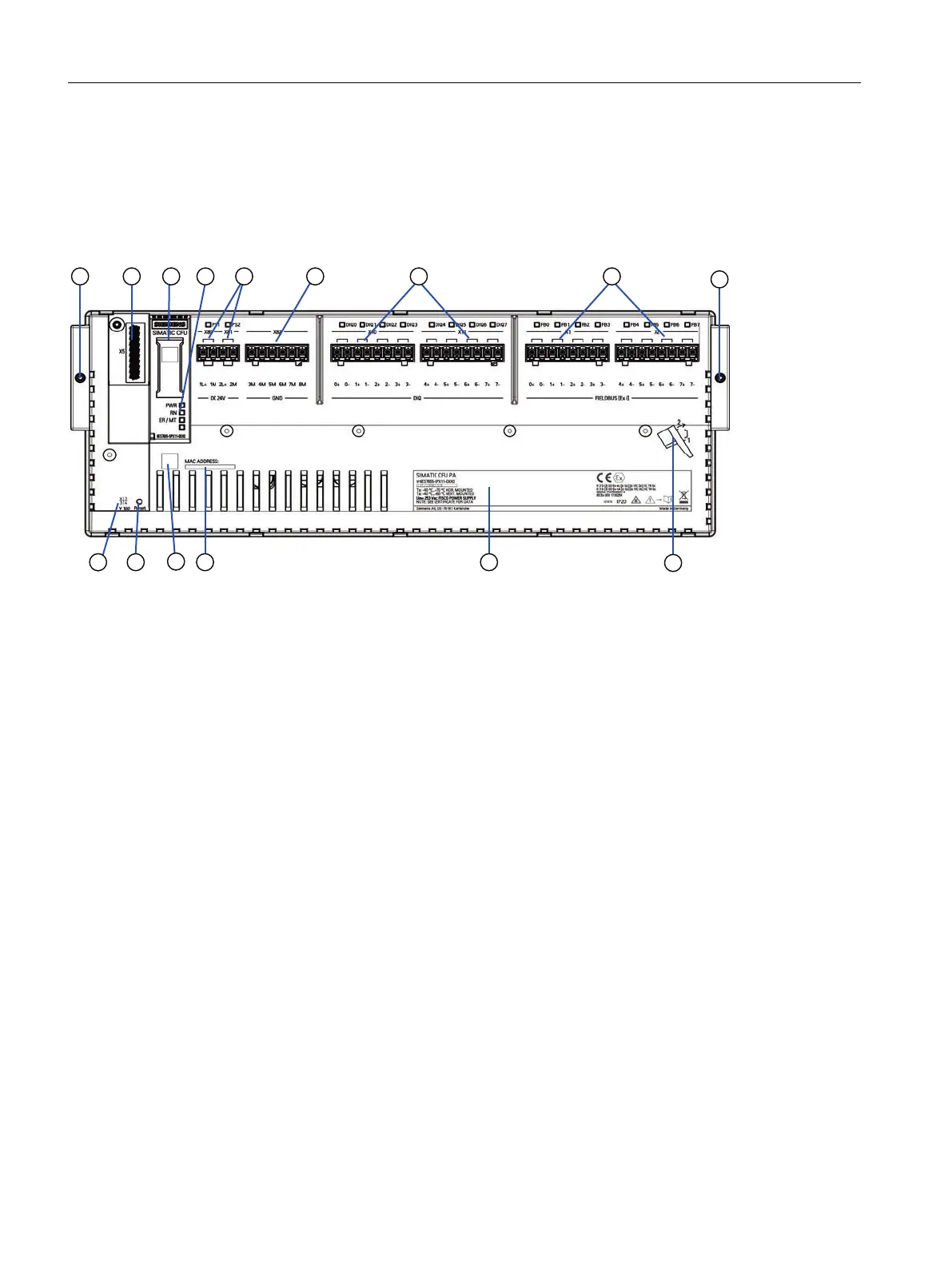
The following figure shows the front view of the CFU using the CFU PA as an example.
Functional elements Additional elements
1 Slot X5: Connection for a BusAdapter A
B
C
D
E
F
G
Locking the CFU on the mounting rail
Labeling strips on interface dome
Product version
2D matrix code (QR code / EAN code)
MAC address
Rating plate
Assembly instruction (latch onto the mounting rail
from below)
2 Diagnostic LEDs on interface dome
3 Slots X80 and X81: 24 V DC; power supply PS1/ PS2 (re‐
dundant connection possible)
4 Slot X82: GND: Connection for reference potential (ground)
5 Slot X10/X11: DIQ;
Connections of freely configurable channels DIQ<n>:
● <n>+ signal line
● <n>- signal line
6 CFU PA: Slot X1/X2: FIELDBUS;
connections for one field device each.
Spur line FB<n>: Max. 120 m length; with automatic bus ter‐
minator
● <n>+ data cable (red)
● <n>- data cable (green)
CFU DIQ: Slot X12/X13: DIQ;
Connections of freely configurable channels DIQ<n>:
● <n>+ signal line
● <n>- signal line
7 Reset: Restore delivery state - reset to factory settings:
Product overview
3.3 Front view of the CFU
SIMATIC CFU
20 Commissioning Manual, 08/2019, A5E39252870-AD