Input area
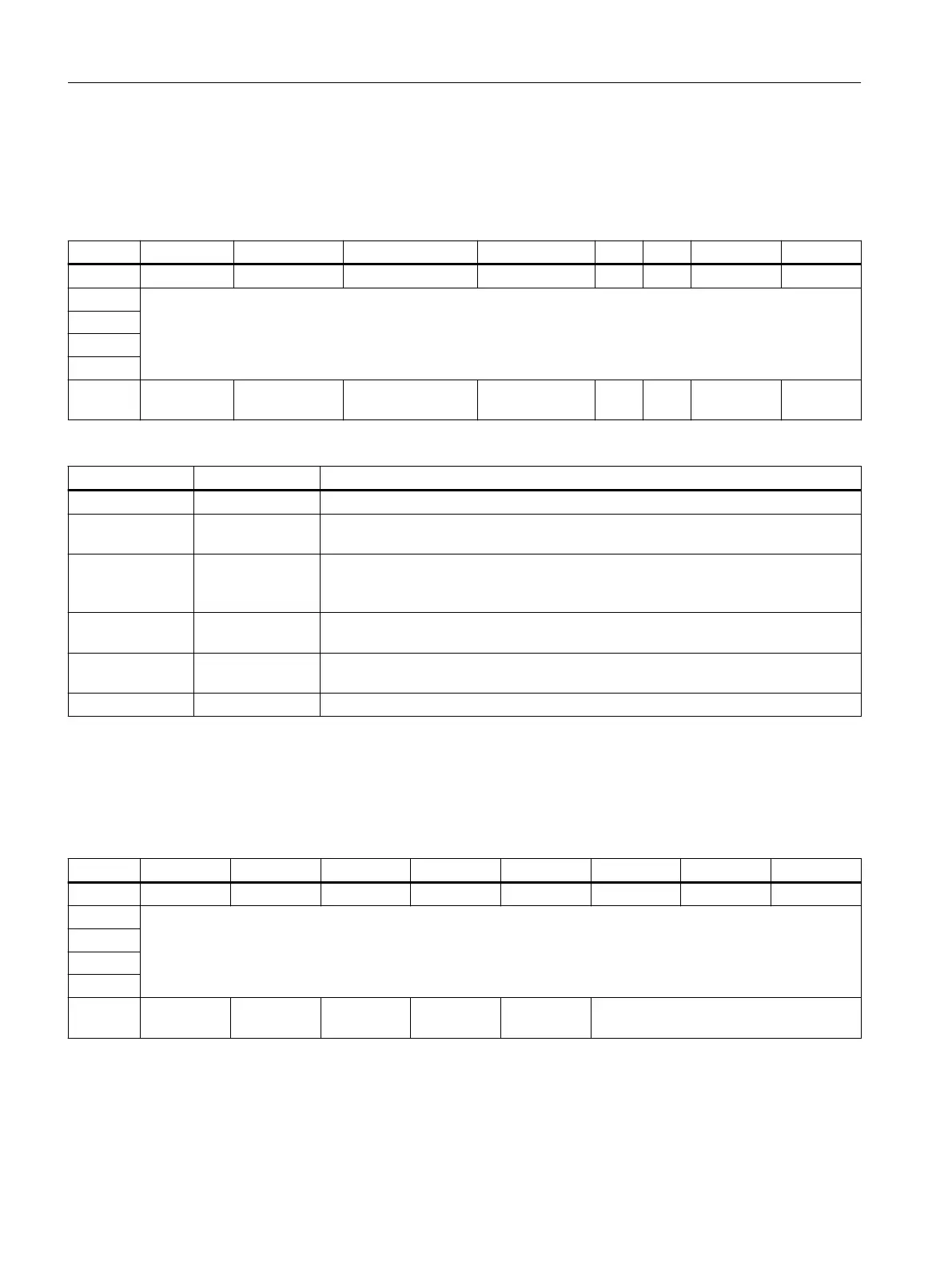
The table shows the allocation of the address space of the feedback interface.
Table A-13 Address space of the CFU PA with submodule "DIQ8 DC24V/0.5A, Counter"
IB x + 7 6 5 4 3 2 1 0
0 DI7 DI6 DI5 DI4 DI3 DI2 DI1 DI0
1 Count value 0 / Frequency value 0
2
3
4
5 LD_ER‐
ROR_0
LD_STS_SLO
T_0
STS_M_INTER‐
VAL_0
STS_SW_GATE
_0
- - STS_GATE
_0
STS_DQ_
0
IB 5 Action Meaning
1xxx xxx LD_ERROR_<x> Error in the control byte or load value is greater than high counting limit
x1xx xxx LD_STS_SLOT_<
x>
A status change of LD_STS_SLOT_<x> shows that a valid load request (LD_SLOT)
has been detected and executed.
xx1x xxx STS_M_INTER‐
VAL_<x>
Only in "Frequency measurement" operating mode (channel 0)
Status of the frequency value: (0 = frequency value is invalid; 1 = frequency value is
valid)
xxx1 xxx STS_SW_GATE_
<x>
Status of the SW_GATE mirrored
xxxx xx1x STS_GATE_<x> Status of the internal gate (0 = gate closed, 1 = gate open), depending on the SW and
HW gate, when the HW gate is activated.
xxxx xxx1 STS_DQ_<x> Logic for the comparison event DQ from the parameters
Output area
The table shows the allocation of the address space of the control interface.
Table A-14 Address space of the CFU PA with submodule "DIQ8 DC24V/0.5A, Counter"
QB x + 7 6 5 4 3 2 1 0
0 DQ7 DQ6 DQ5 DQ4 DQ3 DQ2 DQ1 DQ0
1 Load value 0
2
3
4
5 - - - - SW_GATE_
0
LD_SLOT_0
Appendix
A.9 Drivers, parameters, diagnostic messages and address space
SIMATIC CFU
196 Commissioning Manual, 08/2019, A5E39252870-AD