The following tables show the wiring schemes, depending on how the freely configurable
channels are used.
● Digital input
● Digital output
You can find information on connecting the cables in section "Selecting connection system
(Page 62)".
Note
Diagnostics Wire break
If you use a simple encoder contact, you must observe the following:
In order to detect a wire break, you must connect a resistor parallel to the encoder contact
(sensor resistance for wire break diagnostics: 15 kΩ to 18 kΩ).
Digital input
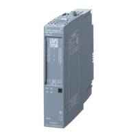
Table 7-2 Wiring variant "Digital input with 1-wire interface"
Wiring scheme Terminals Connection
● <n>+: Sensor supply, channel DI<n>+
● <n>-, <n+1>-,....
Multiple input signals DI<n>-, DI<n+1>-,....
One sensor supply for multiple
channels
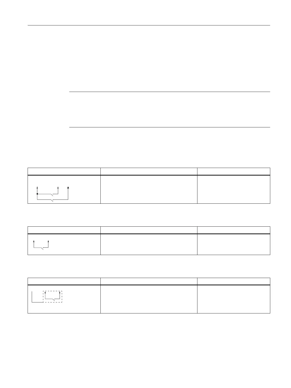
Table 7-3 Wiring variant "Digital input with 2-wire interface"
Wiring scheme Terminals Connection
● <n>+: Associated sensor supply,
channel DI<n>+
● <n>-: Input signal, channel DI<n>-
One sensor supply for one channel
Table 7-4 Wiring variant "Digital input with 3-wire interface"
Wiring scheme Terminals Connection
● M: Reference potential for the sensor supply
● <n>+: Associated sensor supply,
channel DI<n>+
● <n>-: Input signal, channel DI<n>-
One sensor supply for one channel
Connecting
7.4 Connecting the device to the CFU (PROFIBUS PA field device, sensor, actuator)
SIMATIC CFU
Commissioning Manual, 08/2019, A5E39252870-AD 61