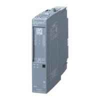
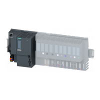
Tab Settings in the "Properties..." dialog box of the DIQ area
Addresses
(no change
necessary in
PCS 7)
You can adapt the following parameters:
● Start Addresses: Areas for inputs and outputs
● Process image
● HW Interrupt Triggers
Tab Settings in the "Properties..." dialog box of the DIQ area
Parameters Module-specific parameters
● Diagnostics Missing Supply Voltage
● Actuator shutdown (module-specific - requires free DI channel)
– Monitoring channel
– Switch off at signal level
Parameter Cross-channel parameters *
● Channel activated
● Channel type
● Diagnostics Wire Break
● Diagnostics Short-Circuit to Ground
● Diagnostics Short-Circuit to L+
● Reaction to CPU STOP
Parameter Parameters for the DIQ channels
● Channel activated
● Channel type: Selection DI / DQ
● Diagnostics Wire Break
● Diagnostics Short-Circuit to Ground
● Diagnostics Short-Circuit to L+ (only relevant for channel type "DQ")
● Reaction to CPU STOP (only relevant for channel type "DQ")
● Operating mode: Counter or frequency measurement (see "Introduction to counting
and frequency measurement (Page 36)")
(CFU DIQ: Channels 0 and 1; CFU PA: Channel 0)
You will find the parameters for this in the following table "Parameters for operating
mode: Counter or frequency measurement".
* Cross-channel settings have no effect on channels with special functions (counter channels, monitoring
channel of the actuator shutdown).
Note
Diagnostics Wire break
If you use a simple encoder contact, you must observe the following:
In order to detect a wire break, you must connect a resistor parallel to the encoder contact
(sensor resistance for wire break diagnostics: 15 kΩ to 18 kΩ).
Commissioning
8.8 Commissioning (offline)
SIMATIC CFU
Commissioning Manual, 08/2019, A5E39252870-AD 95
 Loading...


