Expanding and assigning parameters to the device
6.2 Expansion cards
SIMATIC IPC647E
Operating Instructions, 11/2018, A5E45589180-AA
91
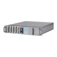
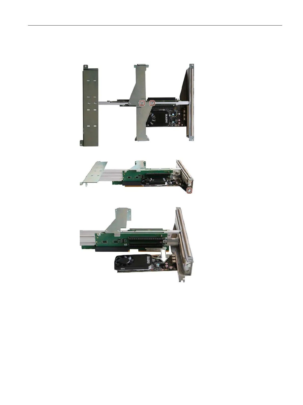
Procedure - Removal
1. Remove the marked screws.
2. Remove the marked screws.
3. Remove the expansion cards without tilting from the slot
4. If necessary, mount a slot blank at the removal location.