6 NC Machine Data (NC MD), NC Setting Data (NC SD) 07.97
6.2 General machine data (general data)
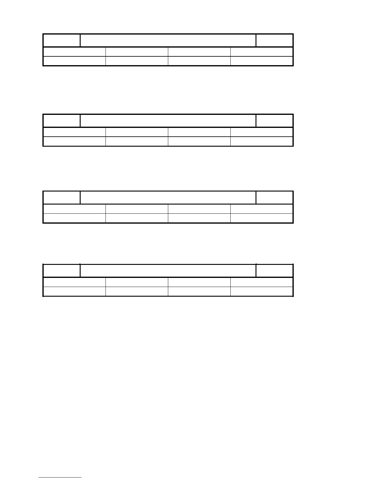
Minimum reduction factor (as from SW 6)
335
Default value Lower input limit Upper input limit Units
100 0 100 %
Active
at once
The minimum reduction factor is entered as a percentage in the general machine data.
The actual path velocity is adapted to the new set path velocity by way of the actual path
acceleration.
Velocity increase factor (as from SW 6)
336
Default value Lower input limit Upper input limit Units
0 0 10 000 0.01·%/T
IPO
Active on
at once
The velocity increase factor is the value in percent per IP cycle by which the reduction factor
is again increased to 100% after failure to reach the hysteresis threshold of the following axis
velocity.
2nd MCS offset in X coordinates (as from SW 6)
337
Default value Lower input limit Upper input limit Units
0 0 99 999 999 MS
POWER ON
Note:
For further information see description of the function collision monitoring.
2nd MCS offset in Y coordinates (as from SW 6)
338
Default value Lower input limit Upper input limit Units
0 0 99 999 999 MS
POWER ON
Note:
For further information see description of the function collision monitoring.
6–26 ©
Siemens AG 1992 All Rights Reserved 6FC5197- AA50
SINUMERIK 840C (IA)