6 NC Machine Data (NC MD), NC Setting Data (NC SD) 09.95
6.7.1 Axis-specific MD 2 (axial data 2)
If the calculated setpoint speed/setpoint acceleration of the following axis is greater than the
defined values, the corresponding interface signals are set at the PLC interface.
If, for example, 50 is entered in MD 276* as the acceleration value, interface signal
”ACCELERATION WARNING THRESHOLD REACHED” is set if 45 is exceeded in the
standard setting.
More detailed information is given in the functional description of the electronic gearbox.
Delay controlled follow-up
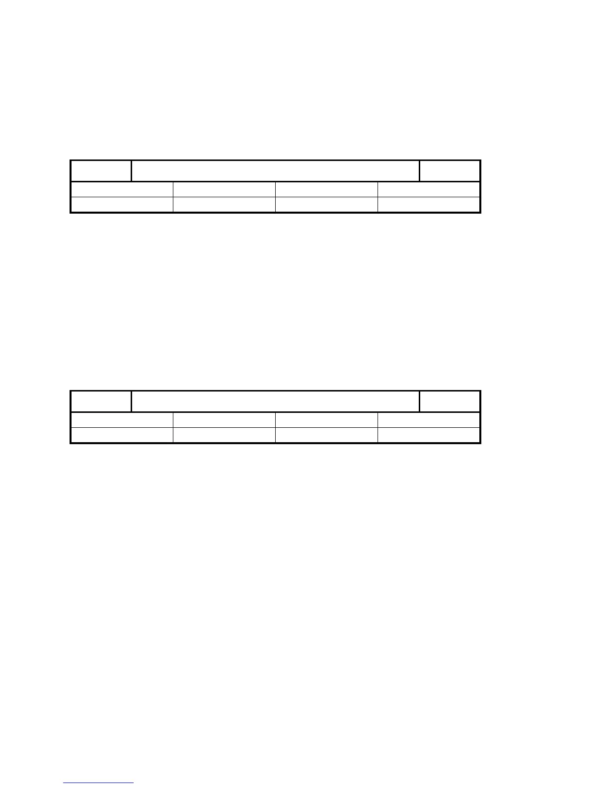
1452*
Default value Lower input limit Upper input limit Units
16 000 0 16 000 1 (ms)
Active on
NC Stop
If a fault occurs with the leading axes, the following axis goes into follow-up mode, i.e.
traverses with actual values as the control value (see the functional description of the
electronic gearbox, "Maintenance of link during faults"). After the delay shown above, the
following spindle switches from "controlled follow-up" to "normal follow-up" (follow-up mode).
Effect of the input values (different cases):
0: No controlled follow-up;
immediate normal follow-up
1...15000: Initial controlled follow-up;
switchover to normal follow-up after the delay
15001 and higher: Always controlled follow-up; no switchover to normal follow-up
Default setting link type
1456*
Default value Lower input limit Upper input limit Units
0 – 3 4
1)
–
Active on
Power On
This machine data only applies to leading axes.
Type of link:
0 No default
1 Setpoint position link
2 Actual position link
3 Setpoint position link (with simulated actual values of the leading drives; the compensatory
controller only reacts to following axis faults.
4 Actual position link/setpoint speed link
1)
The compensatory controller can be activated/deactivated via the PLC signals "Compensatory
controller ON/OFF".
The machine data is used for two applications.
_______
1) As from SW 4
6–176 ©
Siemens AG 1992 All Rights Reserved 6FC5197- AA50
SINUMERIK 840C (IA)