4-56
1010GCNFM-3C
Section 4
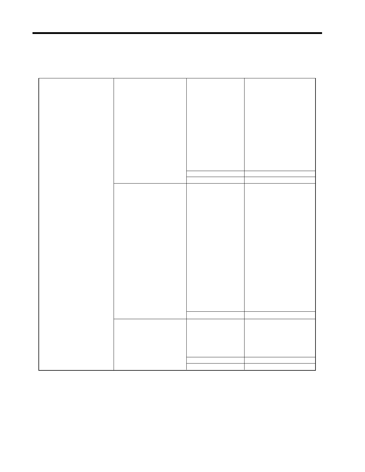
THE I/O DATA CONTROL MENU STRUCTURE
(Note: For Dual Path flowmeters: “1” = Path 1, “2” = Path 2 and “S” represents the system or average
channel. These characters appear to the left of the option list parameter.)
I/O Data Control Analog Output Setup Io1 - Io2 Vfo
Vfo2
Vfab
T1
Iin1
Iin2
Iin3
Iin4
Base S.G.
Viscosity Vsg
Vs
Valc
Vtrb
Vsg
Vo1/2 *See Io option list
Pgen1/2** *See Io option list
Relay Setup Relay 1 Off
Power On
S.G.
Base S.G.
High Viscosity
Low Viscosity
Hi Temperature
Low Temperature
High Flow
Low Flow
Flow Alarm
Fault Alarm
Spacing
Turbulence
Interface
Reverse Flow
BatchTot
Pos Total
Neg Total
Soft Fault
Relay 2, 3, 4 *See Relay 1 list
Analog Input Setup Iin1 to lin4 Off
Aux
PSIA
BARA
DEG F
DEG C
4 mA *numeric entry
20 mA *numeric entry
Ú
Ú
Ú
Ú
Ú
Ú
Ö
Ö
Ö
Ö
ÖÖ
Ö
Ö
Ö
Ö
Ö
Ö
Ö
Ö
Ö
Ö
Ö
Ö
Ö
Ú
Ú
Ú
Ú
*The Dual Path meter has four analog inputs (Iin1-Iin4), six analog outputs (Io1-Io2), two Vo, two Pgen
and four Relay functions.
** Not present in Custody Transfer flowmeters (see paragraph 4.7 Data Span/Set/Cal Menu).
 Loading...


