4-66
1010GCNFM-3C
Section 4
Introduction to [HF] Menu Item
All FUG1010 GCN flowmeters with version 3.01.02 and later operating systems include a new Diagnostics
Menu item that permits the entry of a flow registration correction parameter labeled [HF]. This “HF”
parameter is the input for a proprietary algorithm which automatically compensates for signal beam
blowing in pipes utilizing either 1011 clamp-on or insert transducers, thereby extending the upper flow
limit of all 1011 flowmeters. This algorithm provides the most benefit for clamp-on gas meters where
high flow velocities and low gas sound velocities create the most challenging conditions for digital signal
processing routines.
Using the [HF] Menu Item
Two methods for adjusting this parameter are provided via the [HF] menu cell, located within the
“Diagnostics / Site Setup” submenu. The “Manual” method provides direct entry of this parameter and is
primarily intended for the advanced user, whereas the “Automatic” method allows the FUG1010GCN
flowmeter to automatically measure the required correction and install the parameter.
Guidelines for using the [HF] menu item are described below:
z This menu is only accessible for the transducer channels, not the virtual (average flow) channel
of the flowmeter. (i.e., Diagnostics Path 1 or Path 2, but not Path 1 & 2).
z The FUG1010GCN flowmeter will inhibit the “Automatic” installation of the [HF] parameter if the
flow rate is insufficient (too low) to accurately measure the required correction. If the maximum
flow rate for the application is relatively low then this correction should not be required.
z If the flow rate is very high and the flowmeter is reporting erroneous or unstable flow, then the
flowmeter may already be having trouble resolving the upstream and downstream signals. In
this event, it may be necessary to first lower the flow rate to a moderate level before performing
the “Automatic” HF adjustment. Once this is done the flowmeter should be able to properly
measure the highest flow rates without problems.
z The limits of the “HF” parameter are +/- 0.7 and
any attempt to manually install a larger value
will cause the flowmeter to abort the installation of the parameter.
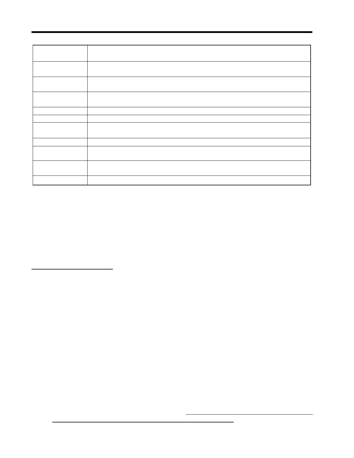
fx (drive) Current Transmit drive code selected during Initial Makeup. The drive code
controls the sonic transmit signal.
N (burst length) Transmit burst duration selected during Initial Makeup. To change N count press
<Right Arrow>. At equal sign enter numeric value (1 to 9 only).
Ltn (in/mm) Spacing distance between the transducers. It will be in inches or millimeters,
depending on default units.
Vfmax The flow velocity (in selected units) corresponding to one whole cycle offset
between upstream and downstream receive signals.
Vs max m/s Maximum correctly calibrated Vs for current transducer spacing.
Vs min m/s Minimum correctly calibrated Vs for current transducer spacing.
Empty % Value of Empty Alarm Setting. The meter will declare an empty status if signal
strength drops below this value.
Samples/Cycle Digital sampling rate.
Max Damping Maximum signal damping. Use to average digital data when an unstable
condition occurs.
Min Damping Minimum signal damping. Use to average digital data when an unstable condi-
tion occurs.
HF Flow registration correction parameter.
SITE SETUP MENU ITEMS
 Loading...


