1-2
1010GCNFM-3CSection 1
1.3 THEORY OF OPERATION
1.3.1 INTRODUCTION
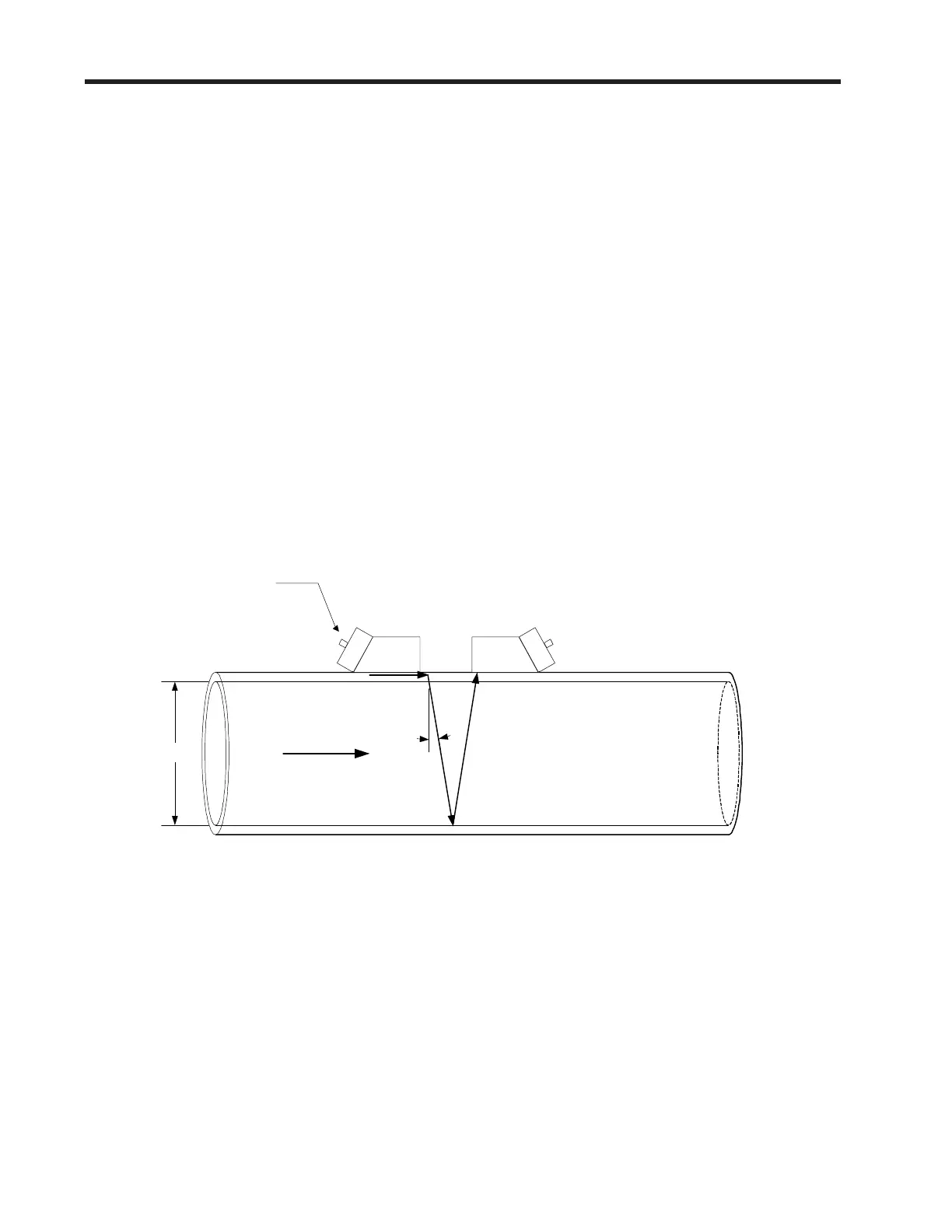
The FUG1010GCN Clamp-on Gas meter relies on the same Digitally Coded MultiPulse transit-time tech-
nology used in our patented 1010 line of liquid flowmeters. Two Wide-Beam ultrasonic transducers per
measuring path, alternating as transmitter and receiver, are used to interrogate the gas flowing within
the metering section. The resulting time of arrival for each direction of transmit (upstream and down-
stream) is then measured using a highly accurate and stable digital phase detection circuit.
Using this detection scheme, the FUG1010GCN Gas flowmeter is capable of resolving the relative tran-
sit-time difference (dT) to within ±100 psec. Considering typical gas flow transit-time differences ranging
from 100x10
3
to 10x10
6
psec, the FUG1010GCN flowmeter is capable of providing an exceptional turn-
down ratio. The FUG1010GCN also incorporates a correlation technique which enables the system to
detect very high flow velocities with the same high degree of resolution. The 1010 ultrasonic transduc-
ers are designed with sufficient beam divergence characteristics to insure that the receive transducer
will always have sufficient signal to maintain operation under conditions of high beam blowing associ-
ated with high flow velocities.
With accurate signal arrival time available, the flowmeter can compute the raw flow velocity from the
measured upstream and downstream transit times.
Pipe ID
Flow
Vector
VOS
Ø °
Ø ° = sin
-1
(VOS /
hase
)
T
L
= 2 * ID / (VOS * cos(
Ø))
V
F
= V
phase
* DT / (2 * T
L
)
VOS = Velocity of Sound in Gas
V
phase
= Phase Velocity of Transducer
ID = Pipe Inside Diameter
T
L
= Transit time in Gas
DT = Measured Transit-Time difference
Where:
Controlotron
Wide Beam
TM
Transducers
 Loading...


