5-1
1010GCNFM-3CSection 5
5. HARDWARE INSTALLATION GUIDE
5.1 PREPARING TO MOUNT THE TRANSDUCERS
Installing the transducers is fairly straightforward. However, careful planning will avoid any snags that
may delay the installation. Previously, based on the input you fed into the meter’s computer, it had
recommended the transducers size, mounting option and spacing. With the transducers at hand, we are
now ready to mount them. But first, some very important preliminary work must be done which consists
of:
z Selecting a mounting option for your application including clamp-on or weld seal (see Appendix B).
z Selecting a location on the pipe.
z Preparing the pipe to accept the transducers.
z Selecting transducer couplant type such as CC128 or CC129A Dry Film couplant (see Appendix A
and Recommended Sonic Couplant Compounds table).
NOTE: When installing transducers, do not key in the V/M (Version/Modification) label number
as the Transducer Size.
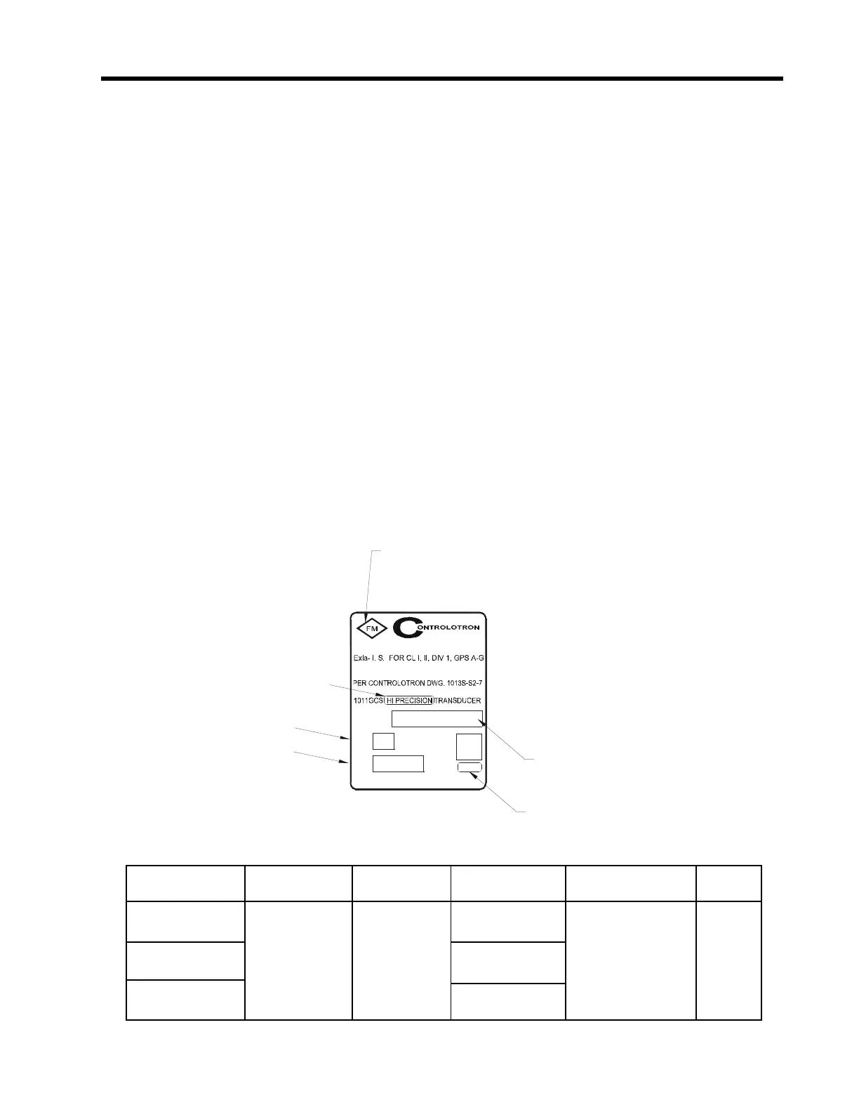
5.1.1 HOW TO IDENTIFY 1011G TRANSDUCERS AND MOUNTING HARDWARE
1011G series of universal gas transducers and mounting frames can easily be identified by the label in-
formation and Transducer Code table as shown below:
1011G Transducer code and operating limitations:
Transducer Code Frequency Transducer Operating Maximum Wetted
Range Description Temp Range Operating Pressure Material
1011GCSa-bT1-c 3 Mhz to 160 Khz Clamp-On -40 to 150 deg F To limit of Spool None
(external mount) (-40 to 65 deg C) Flange Rating
1011GCSa-bT2-c 30 to 220 deg F
(-1 to 104 deg C)
1011GCSa-bT3-c 90 to 250 deg F
(32 to 121 deg C)
Where: a = Precision code, b = Size and frequency code, c = Safety code
MADE IN USA
V/M
S/N
1011GCS
SIZE
HAU PPAUGE, N Y 11 78 8
APPROVED
SUITABLE FOR CL II, DIV 2, GPS F,G
N.I. FOR CL I, DIV 2, GPS A-D
FM Approval identification
Transducer Type
Version/Modification Number
Serial Number
Transducer Size
Transducer Code - see table below
 Loading...


