2-2
1010GCNFM-3C
Section 2
z Plug input power connector (P10) into connector J10 and secure using two captive connector mounting
screws as indicated above.
z Pull wires through flowmeter case cable hole.
z Replace access cover.
z Place power ON/OFF switch to the OFF position.
z Connect the power cables to the appropriate power source (100-250 VAC @ 50/60 Hz or 9-36
VDC).
z Place power ON/OFF switch to the ON position and power up unit. If unit is operational, turn power off
and install transducer cables.
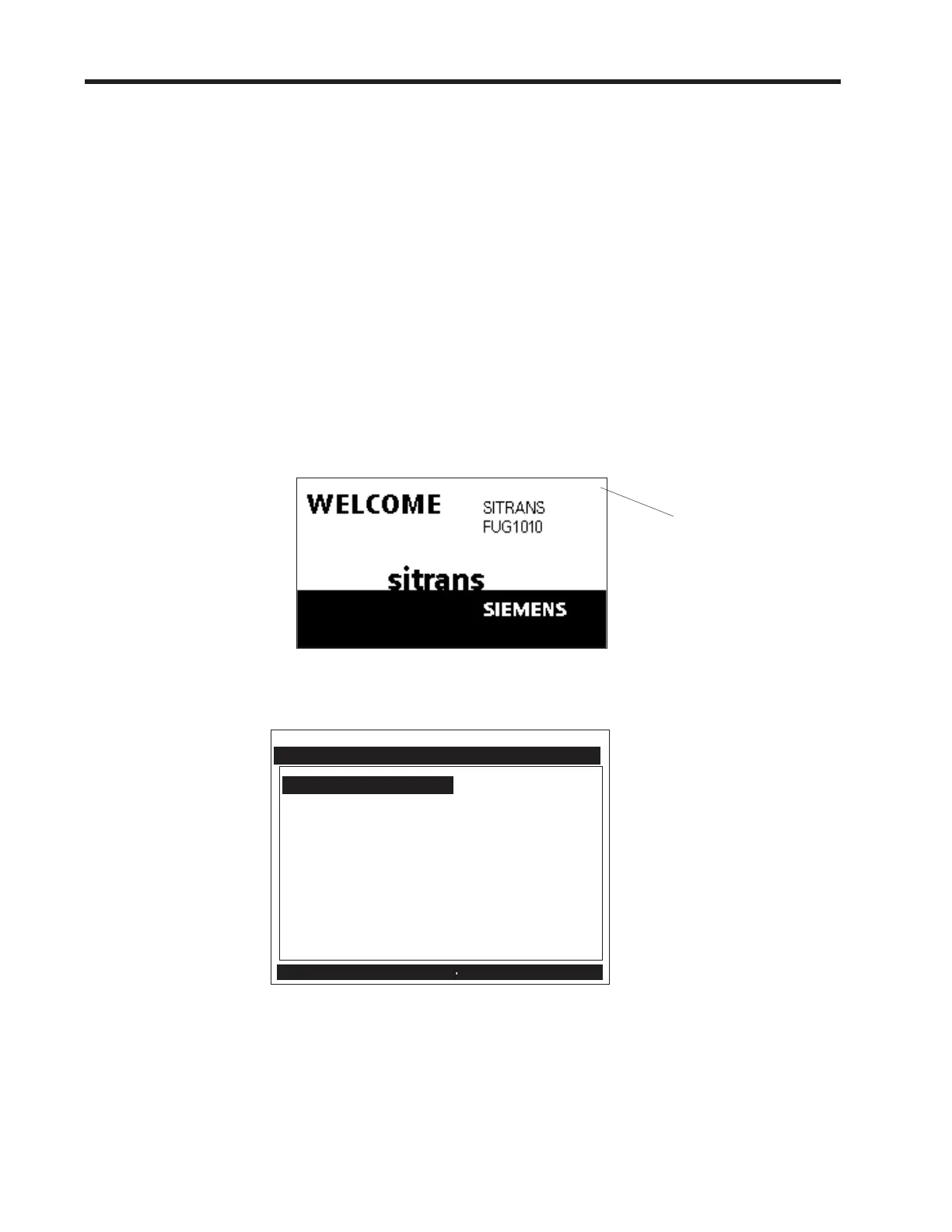
2.3 GRAPHIC DISPLAY SETTINGS
z Within 30 seconds of power-up the flowmeter main display will become active and a Siemens graphic
will appear. The screen also identifies the software version of the unit as shown below.
z Proceed to Section 3 - Getting Started to become familier with the Installation Menu.
z Press the <MENU> button and the Installation Menu will appear.
Siemens Dual Path SITE 1
Channel/Path Setup
Pipe Data 7.900
Gas Parameters
Pick/Install Meter
Operation Adjust
Flow/Total Units
Data Span/Set/Cal
Stripchart Setup
Datalogger Setup
I/O Data Control
Diagnostic Data
Clamp-on Gas
Create-Name-Recall-Enable & Delete Site
ver. 3.01.00
Software
Version
(x.xx.xx)
 Loading...


