5-6
1010GCNFM-3C
Section 5
5.3 DIRECT MODE - MOUNTING FRAMES, SPACER BAR AND SPACING GUIDES
The combination of mounting frames, spacer bar and spacing guides is the recommended way to mount
Direct Mode transducers. The mounting frame establishes the axial alignment of the transducers, and
allows you to remove and replace either transducer while preserving their exact mounting location.
For Direct Mode mounting, you will use a spacer bar to establish the distance between transducers and
a spacing guide to easily locate the transducers at the nine o’clock and three o’clock positions. Should the
distance between transducers be beyond the span of a spacer bar, a measuring tape can be used. The
Mylar spacing guide comes in various lengths and widths to accommodate most pipe sizes (see list
below).
Spacing Guide P/N Size
1012-145-1A 2" x 26" (50.8 x 660.4 mm)
1012-145-1 2" x 45" (50.8 x 1143.0 mm)
1012-145-2 4" x 81" (101.6 x 2057.4 mm)
1012-145-3 4" x 155" (101.6 x 3937.0 mm)
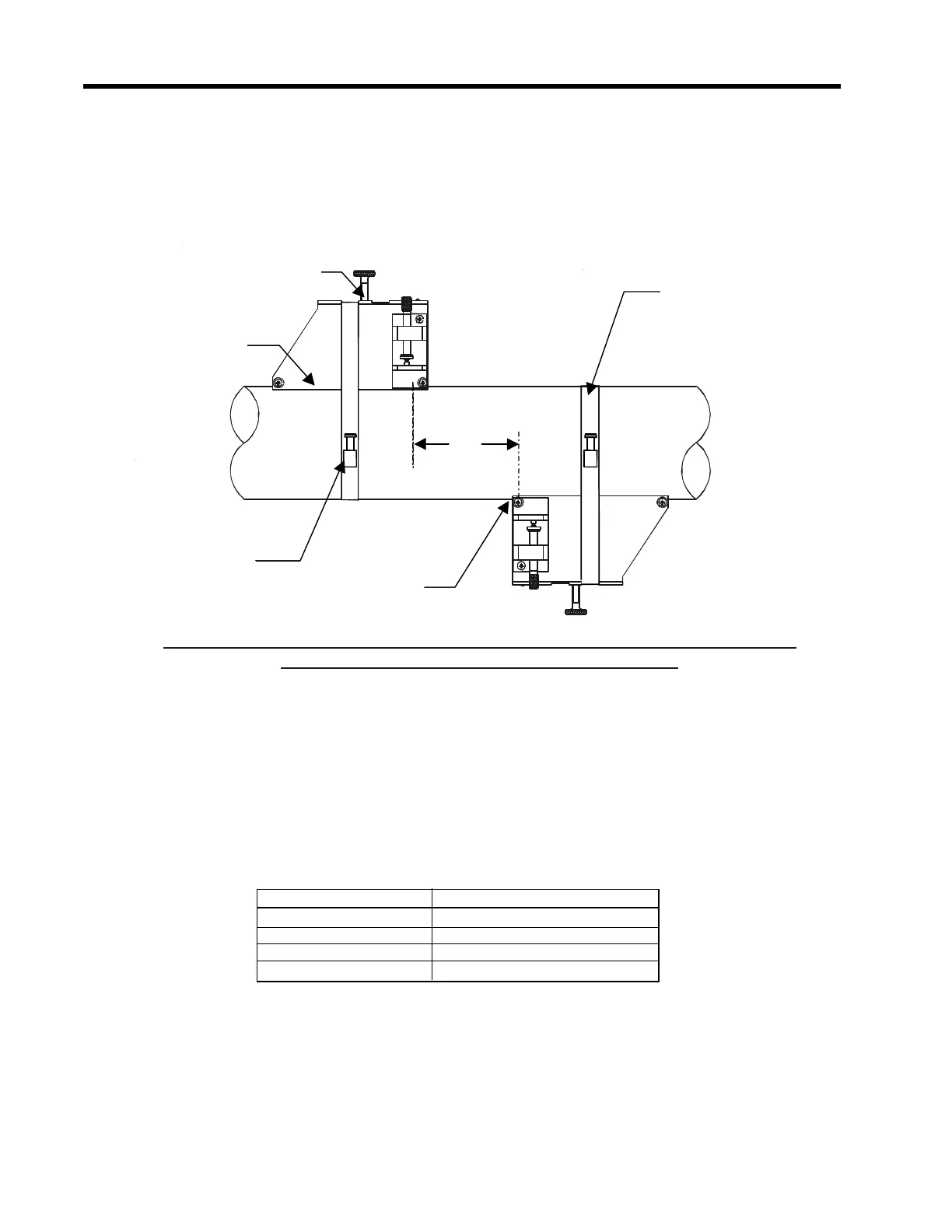
INSTALLATION - DIRECT MODE WITH TRANSDUCERS, MOUNTING FRAMES
SPACER BAR (Not Shown) AND SPACING GUIDE
Ltn
Transducer
Clamping
Scre
Mounting
Frame
Mounting
Strap
Ltn
Reference
otc
Mounting Strap
Adjusting Screw
Transducer
Clamping
Screw
Mounting
Frame
Mounting Strap
Adjusting Screw
Ltn
Reference
Notch
Mounting
Strap
 Loading...


