Manual Addendum
1010FMA-14
3
May 2002
NOTE: The method used to create auxiliary current loops makes it impractical to generate the
2 mA fault current produced by the primary 4-20 mA outputs of the meter.
NOTE: The 1010N-7 Expanded I/O Module auxiliary output signals (Aux Io1 - Aux Io4) geneated
from Pgen1, Pgen2, Vo1 and Vo2 are “mirrored” output currents. For example, if Vo1 is
a 5 Vdc signal then Aux Io3 will be 12 mA.
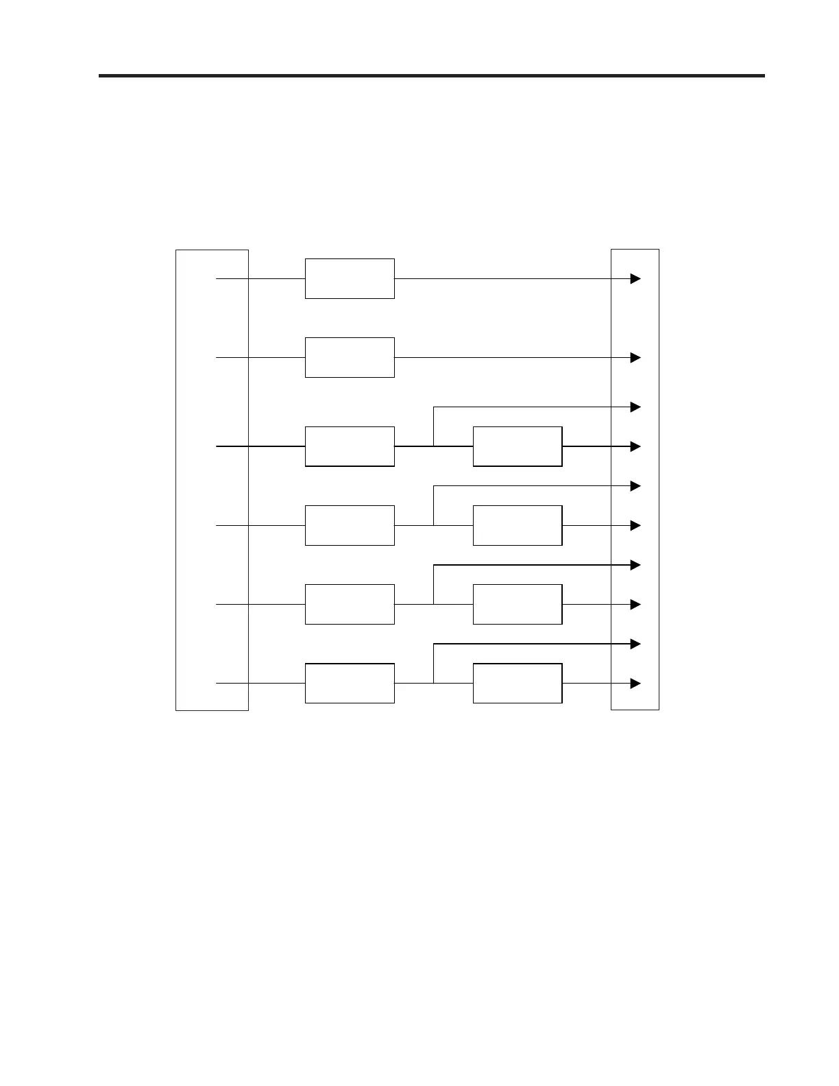
EXPANDED I/O MODULE OPTION PROGRAMMING
The diagram below illustrates the Expanded I/O Module Option programming for a Single Channel
meter with a 1010N-7 Expanded I/O Module.
FLOW COMPUTER
INTERNAL
CONNECTIONS
Io1
Io1
Pgen1
Pgen2
Vo1
Vo2
Aux Io1
Aux Io2
Aux Io3
Aux Io4
OUTPUT
TERMINAL STRIP
z
z
z
z
```
``
`
 Loading...


