4-20
1010GCNFM-3C
Section 4
4.4 THE PICK/INSTALL XDCR MENU
Use this menu after creating a new site setup in the Channel/Path Setup menu, and defining the pipe
parameters in the Pipe Data menu.
Based on pipe data (and optionally application data) entries, the Pick/Install Xdcr menu automatically
identifies the most suitable transducers for the application. It recommends the appropriate mounting
mode (direct or reflect) and lists the Spacer Bar or Mounting Track part number and spacing index.
Ideally, you will be able to use the primary recommendations. However, you can edit the menu entries as
required to accommodate different transducers or mounting configurations.
The flowmeter will adjust its parameters to optimize performance based on your selections. The Ltn
menu cell shows the required spacing distance (in inches or millimeters) between the upstream and
downstream transducers. Use the [Install Completed?] menu cell to inform the flowmeter that you com-
pleted the physical mounting of the transducers. You can define the zero flow values once the transduc-
ers are operational.
NOTE: Before preceeding to mount transducers, it is recommended that Section 5- HARDWARE
INSTALLATION GUIDE be reviewed. Refer to the Pick/Install Xdcr menu and menu struc-
ture shown below for menu cell descriptions and details.
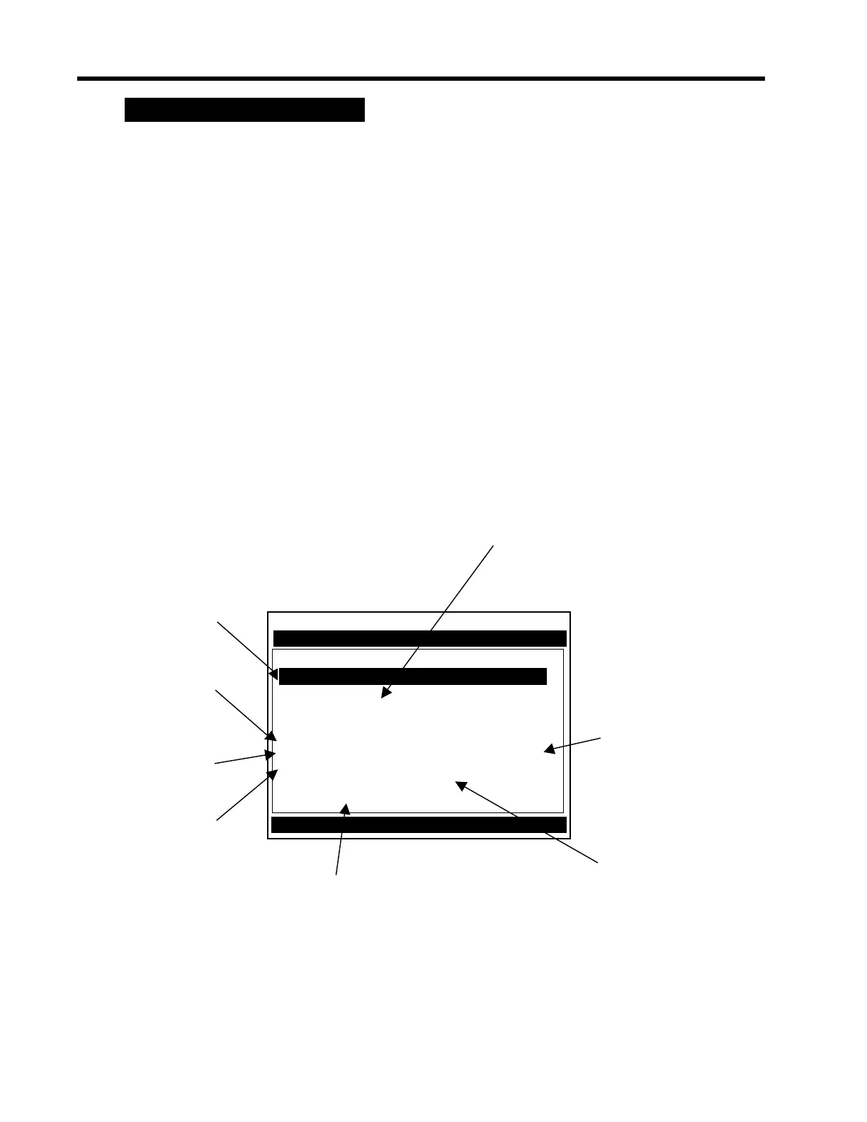
Siemens 2 Channel [1] FLOW1
Scroll List and select desired Model
Pick/Install Xdcr
Use this menu cell to
select the type of
transducer to be
installed.
Install Path 1
Transducer Model 1011HG Hi Prec.
Transducer Size A3H
Xdcr Mount Mode Reflect
Spacing Offset Nominal
Number Index 10
Spacing Method Track 1012TNH
Ltn Value (in) 0.704
Install Completed? Yes
Zero Flow Adjust Actual Zero
This menu cell indicates the
model number of the
appropriate spacer bar for
your transducers and
spacing requirements.
This menu cell
establishes the
spacing between
transducers.
Changing the
Spacing Offset
alters the reported
Number index.
After the transducers
are operating, you can
use this menu cell to
manually set the zero
flow correction.
Once you select the
type, use this menu
cell to specify the
transducer size.
This menu cell
shows the actual
spacing distance
required between
the transducers.
Use this menu cell to
inform the meter that
you completed the
transducer mounting.
 Loading...


