3. Adjust the Noise Level cursor, if required, by pressing the <+> key to increase or <-> key
to decrease.
Note
A delay in response to all keys will occur. This is due to the longer periodic sampling of
the keyboard by the processor while performing FFT’s.
4. Press the <Down Arrow> from Noise Level to advance to the High Limit cursor control. The
<+> and
<-> key are active in this position. Refer to the "Available Adjustments To Spectra
Graph" table for details.
5. Press the <Down Arrow> from High Limit to advance to the Low Limit cursor control. The
<+> and <-> keys are active in this position. Refer to the "Available Adjustments To Spectra
Graph" table for details.
6. Press the <Down Arrow> from Low Limit to advance to the Carrier FX control. The <+> and
<-> keys are active in this position.
7. Press the <Down Arrow> from Carrier FX to advance to the Diagnostic Data Display. The
<+> and <-> keys are active in this position.
8. To exit the Spectra Graph, press the <Menu> key.
9. To display the Digital Flow Display, press the <Menu> key from any Installation Menu
location.
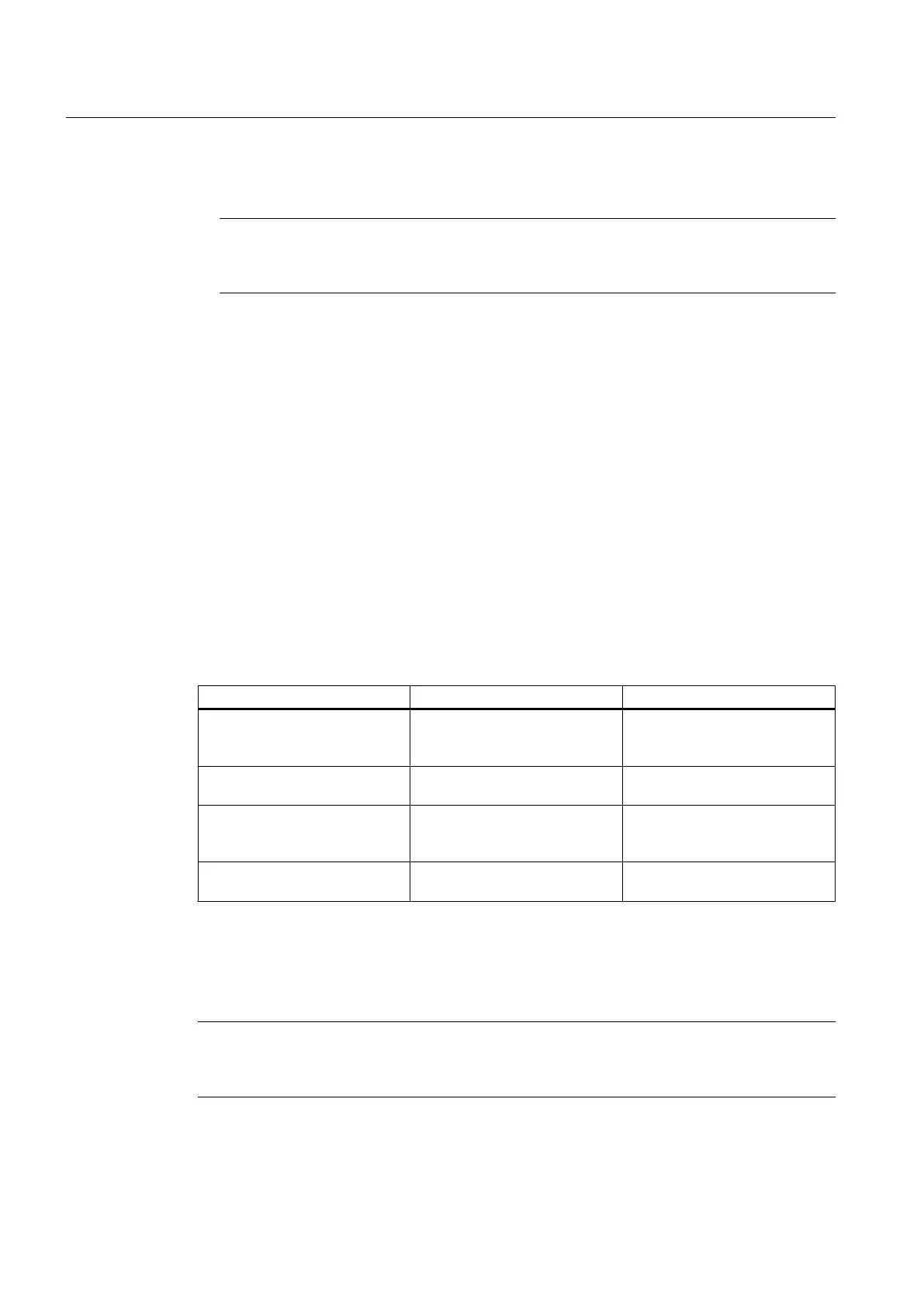
Available Spectra Graph Adjustments
Adjustment Function Notes
Noise Level Set Noise Filter Set to approximately one quarter
the Peak FFT value for typical
flow conditions.
High Limit Low Pass Filter Setting Set to two times the maximum
flow rate.
Low Limit High Pass Filter Set to one half minimum flow if
noise is present. In most cases,
leave at zero.
Carrier Fx Transmit Frequency Code Adjust only under guidance of
technical support staff.
Reflexor Diagnostic Data
The [Diagnostic Data]
menu and the [Application Info] sub menu screen provides one location
where all diagnostic data can be viewed.
Note
Adjustments can not be made on the [Application Info] menu screen. Adjustments can only
be made on the Spectra Graph.
Functions
7.11 Reflexor
FUP1010 IP67 Portable Flowmeter
106
Operating Instructions, 02/2010, A5E02951522A Revision 01

 Loading...


