118
Positioning the NTS Magnets
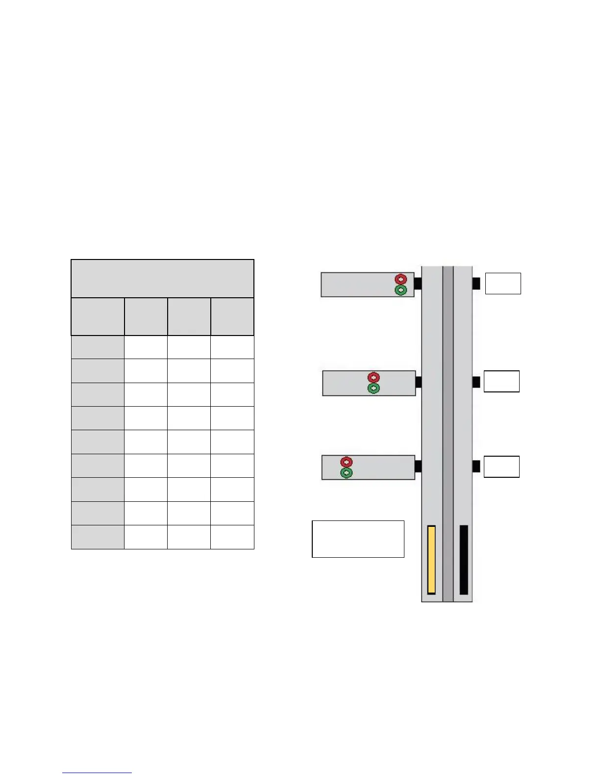
A good starting point for placing the NTS magnet brackets on the rail is by using the Hoistway
Switch Positioning Table from the “Sheet 01: Getting Started” page of the Smartrise drawings.
This table provides a starting distance for the NTS magnets for V3 software controllers and should
be used for reference only.
The actual distance will be determined by using the “NTS Switch Drive Setup” and the “NTS Switch
Position Setup” procedure in the Smartrise Equipment Installation Manual.
The following example shows the initial installation distance using the Hoistway Switch
Positioning Table for a 350FPM car.
Bottom Terminal
DZ Magnets
 Loading...