1250 Frequency Response Analyzer Recording, Learning and Storing Facilities
SH/1250/3 12-15
12.4.3 THE [PLOTTER COMMON] MENU
Set up the (PLOTTER COMMON] page of the DISPLAY/PLOTTER menu.
The five soft keys and their selections are:
MODE SIZE TEXT GRID DEVICE
[point ] [A3] [ on ] [ off ] [ analog ]
[vector] [A4] [ off ] [ on ] [ GPIB-HPGL ]
[ GPIB-ESGL ]
a. MODE
In [point] mode (the default state) plotted points are left unconnected, as required for
this example. If [vector] is SELECTed and ENTERed, the points are joined by
straight lines.
b. SIZE
Select the appropriate size depending on the plotter and paper being used. The
default size is A3.
c. TEXT
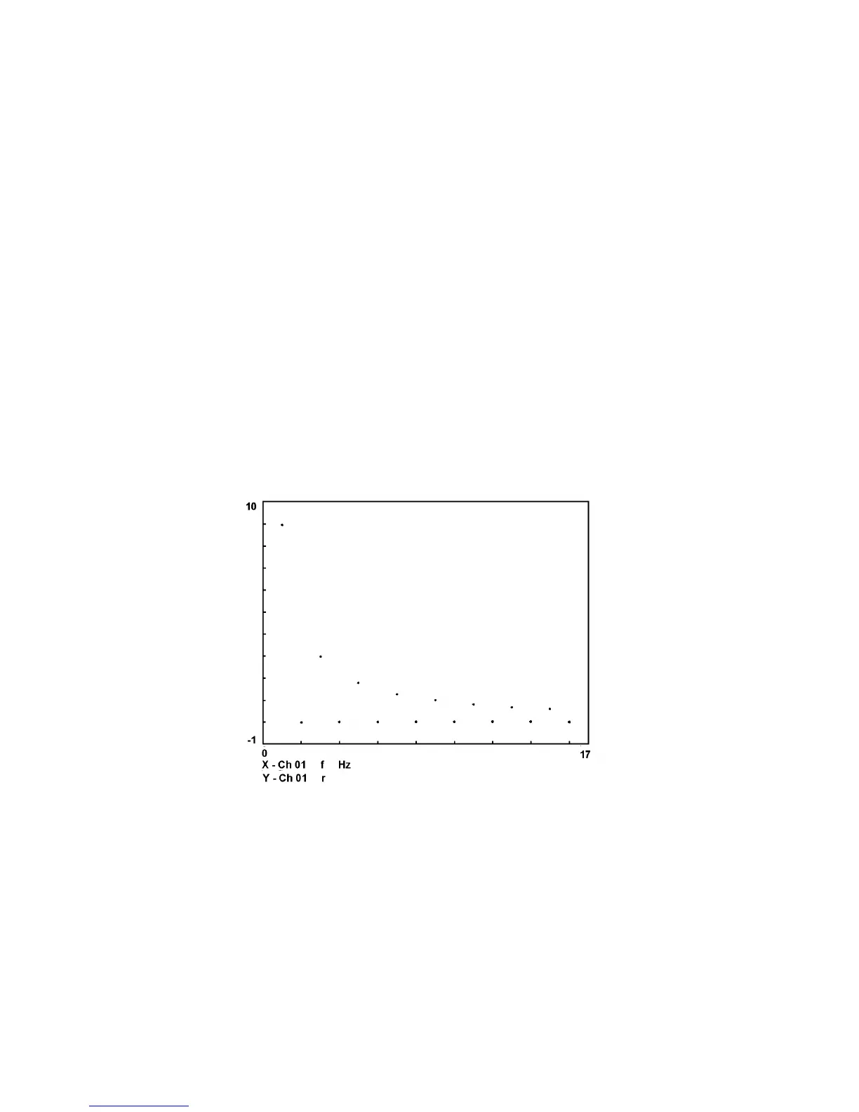
With TEXT 'on' (the default state) during axes plotting, the X- and Y-axes are
annotated with their minimum and maximum values, channels, items, and units if
appropriate. See Fig. 12.2 for an example.
With TEXT 'off', the plotted axes appear without any annotation. Leave TEXT at its
default state for this example plot.
Figure 12.2 - Example plot: 1250 square wave harmonics
d. GRID
With GRID 'off' (the default state) during axes plotting, the divisions along the X and
Y directions of the graph borders are marked by short lines only.
With GRID 'on', the division marks are extended completely across the graph on both
dimensions to form a grid superimposed on the plot. Leave GRID at its default state
for this example plot.
e. DEVICE
Enter the appropriate plotter type connected (see Section 12.4.1 above). The default
device is [analog]; see Chapter 15 "Options" if an analog plotter is being used.