1250 Frequency Response Analyzer Installation
CWB / 1250_Op / Issue 9A 2-3
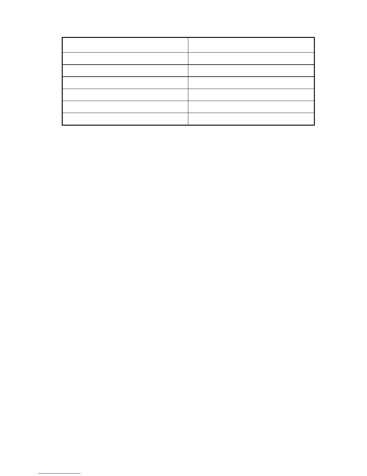
Input / Output Maximum Voltage
Generator outputs 150V, HI or LO to Gnd
Channel inputs 500 V, HI or LO to Gnd
Auxiliary Generator output 150V, HI or LO to Gnd
Modulator/Demodulator carrier inputs 350V peak, 250V rms, HI or LO to Gnd
Synchroniser input 350V peak, 250V rms, HI or LO to Gnd
Generator Stop inputs +7V to Gnd
2.2.1 Electromagnetic Compatibility
When used as described in this manual the 1250B, 1250E and 1254A models meet the
requirements of the EMC Directive, (see Specification in Chapter 17). The 1250 must
not be operated with the inner metal screens removed and any replacement
components must be of the correct type.
When conducting tests where there is a radio-frequency common mode voltage present,
it is strongly recommended that the Synchroniser, Carrier 1 and Carrier 2 inputs use the
differential connection, that is, with both HI and LO connections connected to their
respective sources by screened cables. In this way the signal leads will be screened by
a ground which originates at the 1250 and continues to the signal source.
Data cables connected to the Serial, GPIB and Interface B connectors should have a
braided outer screen, which should be grounded.